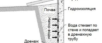
- Design
- Thread type
- Direction of thread being cut
Every craftsman knows what a die or tool is, but it will be very useful for beginners in plumbing to study our article. In it we will give answers to the following questions.
- What are dies and what are they used for?
- What design features does the tool have?
- How is a die different from a lerka?
- What types of dies are used in plumbing?
- What are they made of?
- How to use dies?
Threading [ edit | edit code]
The tap is attached with the tail part to the driver, the working part is inserted into the hole in which, when turning the driver, a thread is cut in a reciprocating motion. The working part of the tap has cutting and calibrating parts. To avoid friction on the workpiece, the rear surface is backed (non-round). The thread profile of the tap must match the profile of the thread being cut.
When cutting threads, sets of two or three taps (rough, medium and finishing), differing in size and profile accuracy, are often used; on viscous materials (for example titanium alloys), sets of five taps are used. To perform most household plumbing work, two taps are enough; these are the sets that are sold in retail trade.
There are taps for blind and through holes.
Taps are made of carbide or high-speed steel.
Taps can be used on lathes, drills and machining centers (machine taps), as well as for manual threading. A machine tap differs from a manual tap in the shape of the lead. The tap is secured on the machine in a special chuck (chuck with axial compensation) or a regular collet chuck with a collet for taps. Also recently, as an alternative to axial compensated chucks, compensated collets have begun to appear, which can be used on a conventional collet chuck.
To obtain internal threads by plastic deformation (rolling), chipless taps (rollers) are used. Their main difference from cutting taps is the absence of chip flutes.
There are also nut taps used to make nuts. This type of tap has a longer shank and lead-in (calibrating) cutting part.
When cutting threads, the tap is pre-lubricated with grease, for example, grease. Periodically turn the tap in the opposite direction to break off the resulting chips. If you use a tap out of order (for example, finishing instead of rough), it can easily break.
A tap is a type of metal-cutting tool that is used to apply internal threads and calibrate existing ones. The application method - manual or automated, depends on the size of the workpiece. In appearance, the tap is similar to a screw or cylindrical roller. The maximum thread diameter is up to 50 mm for both blind and through holes. For the production of taps, steel grades are used: P9, P18, P6M5.
Terms of use
To create a screw on a pipe, you will need a set of appropriate dies, knobs and a special clamp. For thread cutting, the most suitable set of dies is selected depending on the diameter of the pipe and the required pitch of the turns. Some parameters can be determined by visual inspection of the surface, but there must also be appropriate markings on the surface of the housing. Do not forget that the screw being created can be left or right.
The entire process of creating a screw on a pipe can be divided into several main stages:
Work should begin with preparing the pipe. The metal surface must not have rust or serious defects. Cleaning can be done fairly quickly using special devices. A chamfer is removed from the end surface. This work can be done using a file. As with a tap, the surface should be lubricated with oil or some other similar substance. Without a lubricant, high loads may occur during operation, which will lead to deformation of the cutting edge. The die is fixed in a special die holder
Attention is paid to how strong the fastening is, since a high load can be transferred to the main part of the tool. During operation, one hand rotates the tool, the other - presses it. For a tool to cut into metal, there must be a significant impact on it. It is recommended to make two turns in the thread direction and one turn in the opposite direction.
This ensures that the resulting chips are removed from the cutting zone, which facilitates the movement of the tool.
Higher quality threads can only be obtained by using a split die. This is due to the fact that the design has a locking ring with which the diameter is adjusted.
When carrying out work, it should be taken into account that there are several types of screw connections:
- Triangular.
- Trapezoidal.
- Rectangular.
- Persistent.
The thrust type of connection is characterized by the fact that constant one-sided pressure is exerted on the elements being connected. That is why the coils must have high strength. The rectangular type of connection is characterized by the fact that it is used to combine moving structural elements.
In conclusion, we note that there are quite a large number of sets of dies on sale. If thread cutting work is carried out frequently, then you should purchase kits from well-known manufacturers who use high-quality steel when creating tools.
Application
Threading tools are divided into types according to design features and application:
- • manual, where the teeth are arranged in a circle. Used in metalwork and manual cutting;
- • nut, for through holes on nuts. With an extended or curved shank;
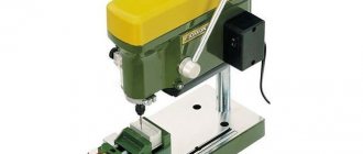
- • machine, for creating blind holes by machine. Processing takes place on lathes;
- • combined, it is possible to use both manual and machine methods of applying threads to the part.
The tool allows you to apply all types of threads - metric, inch, trapezoidal.
Tool selection
Let us note in advance that threads can be cut in different ways.
You can work either manually or by machine. In the first case, as we noted above, you need to have a set of tools with you for creating threads, in the second, the work is carried out on a lathe. Manual threading is recommended if your task is to machine only a few parts. For example, when assembling plumbing equipment, creating household pipelines, etc.
Processing parts on a lathe involves performing large-scale tasks. A person with experience with this type of equipment is able to cut threads on an industrial scale, up to a hundred parts per hour, and sometimes more. However, you are unlikely to need such performance.
Most often, a set of hand tools covers all the household needs of home craftsmen. With their help, you will also be able to cut threads correctly and efficiently, but it will only take more time and effort.
The set of equipment mentioned above is mainly represented by taps and dies, as well as various additional parts.
Features of taps
Taps are cone-shaped or cylindrical parts that are designed for cutting internal threads. In particular, they are used to make threads on pipes, nuts, small washers, various kinds of clamps and even flanges.
The taps are quite convenient to use. They consist of a working and a rear part. The working part has a unique shape and diameter. On its edges there are special incisors or teeth with a certain pitch. The teeth, when rotated, cut the metal in parallel with the removal of chips.
The back side is made in a certain shape, which makes it easier to fix the tap on the working tool.
A variety of taps for household use
Taps with the ability to cut threads without forming chips are also used, but much less often, because they are more expensive.
There are taps:
- Rough;
- Semi-draft;
- Finishing.
Roughers make the first pass, remove most of the chips and form rough grooves for the threads. This is not a full carving yet, but the preparation has already been completed.
Semi-draft models are extremely rare. They are intended for finishing rough grooves, cleaning them and forming a workpiece for a clean thread. Semi-rough taps are used primarily in the manufacture of complex parts.
The last sample, a finishing tap, forms a ready-to-use thread of precise dimensions and shape.
According to the type of actions performed, taps are divided into:
- Metric;
- Nuts;
- Pipe;
- Machine.
Note that taps, as well as dies, can cut threads of different sizes, directions and shapes. It all depends on the chosen equipment model.
Features of dies
A die is a cutting tool that is used when making external threads. The simplest example of an external thread is a bolt. While an example of an internal thread is a nut.
The dies are flat, from the outside they strongly resemble large washers or clamps for machine chucks. Only inside the die there is a cutting attachment with several rows of twisted cutters.
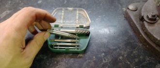
Tap and die, close up
Dies can have different shapes, types of assembly and dimensions. There are both round and square models. Some options are completely solid, others can be disassembled and the cutting attachment can be replaced.
The cutting part consists of three working zones. The two zones located at the edges consist of teeth, while the inner zone is responsible for removing chips and adjusting the direction of rotation.
It is thanks to the inner zone that the dies have a self-tightening property. That is, after several rotations on the pipe, the die is fixed.
You can then rotate it without pressure, since it will tighten in the direction of the thread formation. While the taps must be rotated with force throughout the entire process.
The types of dies are essentially the same as the types of taps. If you bought a large set of tools, you will probably receive several of these parts at once.
Design features
Any type of tap consists of a working area, a neck and a shank. All mechanical work falls on the working area, which in turn has a intake part and two types of teeth - cutting and calibrating. The role of fastener is performed by the shank, which is fixed on machines in a special thread-cutting chuck, and during manual work in a driver or tap holder. A characteristic feature of hand taps is that they come complete with at least 3 pieces. Each with its own working function: roughing, middle and finishing.
How to cut internal threads with a tap
To create internal threads in finished holes, you need to select the appropriate tap according to size and characteristics. Almost all indicators regarding the choice and quality of threads are regulated by the regulatory document GOST 19257-73. Recommendations for work:
- • for products obtained by casting or stamping, additional preparation is required before applying the thread. The hole is countersinked or drilled to increase the diameter;
- • for accurate and high-quality threads, it is recommended to mount the tap shank in chucks with reversible, self-centering and floating properties;
- • all processed workpieces are first chamfered;
- • during the cutting process, cooling and lubricating solutions must be used.
Thread types: metric, inch and pipe.
- Metric - thread parameters are measured in mm, with the corresponding marking “M”.
- Inch - used for conical taps, measured in inches.
- Pipe – for cylindrical taps, threads are applied to pipe connections.
Applying threads using dies
Connection using bolts can easily be called the most popular type of fastener. However, even high-quality carvings will deteriorate over time. And here there are two ways - you can turn to a professional locksmith for help or apply the thread yourself. In any case, for this operation you will need a set of drawers or dies - this is the name given to hand tools for applying external threads. Using them, it is possible to quickly restore worn-out hardware or produce the required part for an existing stud/bolt.
Classification of dies (dies) by design
The first characteristic that distinguishes one die from another is the body design. According to this indicator they are divided into:
- The dies are rounded - their body is a full-fledged ring through which the workpiece is passed. Due to the increased rigidity, the result is a high-quality helical profile on an excellent thread;
- Sliding dies (lerks) - they consist of 2 elements and are intended for the manufacture of threaded areas of different diameters;
- Split dies - their threaded diameter along the run can range from 0.1 - 0.3 millimeters, and therefore they must be used when applying imprecise threads.
Classification by thread direction
Based on this basis, dies can be divided into:
- Left-handed - rarely used and especially in specific auto parts, rotation mechanisms, and in cases where the right-hand thread can unwind;
- Right - the most popular direction, used on screws, bolts, axles.
Classification by profile
According to the profile, the dies can be:
- Metric - have a metric thread, marked with the letter “M”, followed by a number indicating the diameter in millimeters. Standard sizes are up to 68 mm, with each standard corresponding to a large or small pitch (in the Russian Federation this is regulated by GOST 9740);
- Cylindrical pipes - marked with the Latin letter “G”, their threads are measured in inches (relative to the metric system, 1 inch = 2.54 mm);
- Conical pipe - they will be marked with the letter “K”, they are used to obtain a threaded surface in the form of a cone in particularly critical connections that are installed in places where elements work under high pressure (for example, working units of production machines);
- Trapezoidal - their thread cross-section is an equilateral trapezoid. They are used in power pairs where rotation is converted into translational movements (for example, a nut and a lead screw in a bench and machine vice).
Die holders
In order to cut, one die will not be enough. It is also necessary to use an assistant device to hold and clamp the line - it is called a die holder. One such device is immediately designed for several sizes - from small to large. The die is installed inside and held in place by a screw.
Material of manufacture
For the production of dies, high-speed steel R18 or R6M5 is used as standard. They are good in terms of price/quality parameters, have an extended service life and do an excellent job with minor repairs and household work.
Thread cutting technology using dies
Basically, the principle of action is quite simple, however, there are some nuances here:
- At the preparation stage, you need to grind off a small blunt on the end of the part using a file (the tool will cut better);
- Firmly fasten the die in the holder, make sure that it does not rotate;
- Perform two full turns, slightly pressing the lever with your hand;
- After the tool has entered the part, you need to perform 2-3 full turns and one half-turn back - this way the application is done more efficiently.
IMPORTANT! It is necessary to constantly monitor the position of the holder in relation to the element being processed - it must always be perpendicular and not tilted!
Features of choosing a set of dies and taps
First of all, you need to clearly separate all the tools and navigate the set. There are professional versions of the kits, and there are also amateur ones intended for household use.
First, you need to decide on the type of dies/taps. For example, which system is supposed to be used more preferably - inch or metric. In Russia, the metric system is more often used. Here you can visually identify the links of this system by their conical shape and the established metric thread pitch. It is also worth taking into account the fact that the threads of the blade should have a triangular profile - this can be seen from the last turns of the blades. Thus, using such a tool, the nut can be screwed onto the restored thread.
The accuracy of the required cutting will be achieved through split dies, and if precise cutting is not needed, then it makes sense to take a set with solid dies. Of course, most professionals advise purchasing a set that contains all existing types of cutting.
Separately, we need to mention the cases - the sets can be located in convenient plastic or wooden boxes, they allow you to comfortably transport the entire tool. And if necessary, it’s easy to use it.
Regarding the material of manufacture - in this case there is no need to speculate much - the tool, by definition, is made of high-strength high-carbon steel. However, you should still avoid outright counterfeiting - usually Asian “no-name” manufacturers make their sets from soft metals.
Machine and machine-hand taps
To calibrate and create threads in blind and through holes of various shapes, a tool is used - a tap, machine or machine-hand type.
— Machine metal-cutting tools are used to work on lathes, drilling, aggregate and turret machines to cut threads of all types. They process products much faster and can be used for conveyor production and large orders. With this type of equipment you can cut threads in one go if you need threads with pitches of up to three millimeters. Coarse pitch threads are made using several passes using a tap on the metal product.
— Machine-manual equipment can be used to cut threads both manually and using drilling devices (machines). The tool is available in quantities of one or two pieces. In a set of two taps, one metal-cutting tool is used for roughing work, and the other for finishing work. Often a set of machine-manual equipment is used to work with different types of materials: mild steel and cast iron are processed with one tool, and hard steel is processed with two taps. Machine-manual types differ from simply manual thread cutters in the type of shank - there is a square and an annular recess, thanks to which the equipment does not fall out of the chuck during processing of products. A machine-made product for working with metal can make threads in automotive parts, cut fastening threads and small-metric, cylindrical and conical threads. In through armholes and blind ones.
Types and properties of cutters
A metal turning tool consists of a holder and a working head. The quality of parts processing directly depends on these elements. The holder has a rectangular or square cross-section. With its help, the cutter is fixed on the lathe.
The working head is used to process parts. It is composed of various cutting planes and edges. The sharpening angle of the head is determined by the material from which the part is made.
External and internal threads are cut using different types of thread cutting tools.
Threading cutters
The most used ones:
- rod;
- prismatic;
- round.
Rod cutters consist of a rod with a working head. These types come in different profiles. The most wear-resistant are cutters to which carbide working edges are soldered. They do not need frequent sharpening as they remain sharp for a long time.
Prismatic cutters are used to process only the outer side of the blank. Their advantage over rod ones is their ability to process large surfaces. But they should be sharpened more often.
Round cutters are used in the process of cutting internal and external threads. These tools are very easy to use and their scope of use is quite wide. Round cutters allow repeated sharpening.
Round thread cutters
Based on their design differences, metal-cutting tools are divided into several types:
- straight;
- curved;
- bent;
- drawn out.
The top of any threading tool is a rounded head or chamfer. The thread profile is formed by a cutter of the proper configuration. Using curved cutting tools, the threaded thread is cut on the surface of the blank.
Straight incisors are rarely used here. The carving inside the part is made with curved cutters, sometimes straight, fixed in a special holder.
Cutters are divided into categories:
- made of high-speed alloy steel;
- with carbide plates soldered onto the working element;
- cutting devices with replaceable multifaceted inserts mounted on the head.
According to the direction of the screw thread, the tools are differentiated into right-handed and left-handed. When working first, the feed goes from left to right, when working second, the feed goes to the left. The right ones use it more often.
Cutting the thread with a die
Taps - broaches
To obtain large-profile threads in metal products, use a broach tap. It is used to process complex through or trapezoidal holes. Broaches can only be used in a lathe. The thread is cut in one pass along the hole. This tap differs from other types in its more precise design and rigidity. It works in tension rather than compression like conventional threading tools. Due to the broaching function, the thickness of the cut is reduced, and the length of the cutting part is increased.
Nut taps
Nut-type tools are designed for thread cutting in nuts of different diameters. The design of the nut tap is such that the tool does not need to be turned out at the end of the nut hole machining process. Nut accessories can be with different shanks: curved and elongated. With curved ones - used in working with automatic nut-tapping machines. The shank of a nut tap is, in any case, longer than that of other types; this is necessary in order to string nuts onto it as threads are cut into them. This increases speed and productivity.
Damage to the tap - possible causes and their elimination
The instrument in question, naturally, is not entirely durable and is prone to simple obsolescence and natural wear and tear. The most common cases of damage:
- Warping;
- The working opening is too narrow;
- Excessive force applied by the operator to the gate;
- Failure to follow the reverse half-turn rules at the end of each full turn.
If any of the above cases occur, then there is no need to rush and try to run the thread faster or try to skip the tap from the set. All this can result in temporary losses, and therefore all extraction actions should be carried out slowly.
Bench taps
To work with holes of different types and shapes, craftsmen take a set of metalworking taps. Thread-cutting equipment is manufactured in sets that include roughing cone-shaped tools, semi-finishing and finishing cylindrical equipment. Using metalworker's taps you can process the part manually. Using a set of metal-cutting equipment, a master can cut large and metric threads. Taps for metalwork are left and right depending on the direction of their rotation.
Classification of threads
A helical groove cut inside or outside parts in the form of a cone or cylinder is called a thread.
It can be cut manually or on lathes using special tools: taps and dies.
The method of cutting using these methods differs: the machine version involves rotating the workpiece, while in the manual version it is rigidly fixed and the tool itself rotates.
All existing types of thread are divided into several groups:
- Depending on the direction of wrapping, they are either right or left. If you look clockwise, then for the first the groove goes along its course, and for the second - against it.
- Depending on location, there are internal and external threads.
- According to their purpose, there are trapezoidal and rectangular threads that serve to transform rotation into movement. They are called running gear. For normal connection of parts there is a fastening thread.
- The cutting form can be cylindrical or conical. The latter are used to obtain the most airtight connection.
- Depending on the profile of the thread section, there are triangular, rectangular, trapezoidal, and round.
- Single-thread tools with one threaded groove are available. Multi-pass ones have several of them. The number of passes is determined by the number of starts at the end of the workpiece.
What materials are taps made from?
Metal-cutting tool dies are made from high-quality steel of different grades: tool, high-speed, alloy. Modern production technology allows taps to be made from carbide steel and powder steel; in the latter case, the tool is produced by sintering powders. Taps made of carbide alloys are of higher quality, as they are resistant to high temperatures, wear-resistant and can work for a long time at high speeds, which allows processing a large number of metal products. Tools made from steel powders also have their advantage - high strength due to the lower hardness of the tool.
GOST standards
Machine-manual with straight/helical/shortened grooves made of carbon steel are regulated by GOST3266-71-71/GOST17933-72/GOST 17931-72. Nut taps with straight/curved shank are made from low-alloy steel in accordance with GOST1604-71/GOST6951-71. Machine-manual, where the teeth are staggered, made of stainless steel - GOST 17927-71. Nuts with a staggered arrangement and a straight shank (taps made of heat-resistant steel) in accordance with GOST 17929-72. Machine tools with screw or shortened types of grooves (tools made of light alloys) - GOST 17932-72/17930-72.
Preparing for Threading
The hole is prepared in several ways before cutting a thread - by sharpening, grinding or drilling the surface of a metal workpiece. For external threads, the diameter must be reduced by 0.1 - 0.4 millimeters. At the beginning of the section where the thread will be, a chamfer is made by sharpening - this is necessary to dull the entry of the thread. And if the hole is bored before threading, its diameter increases to 0.4 mm. The hole for the thread should be slightly larger in diameter than the diameter of the thread itself - this helps prevent breakage of the thread-cutting equipment.
How to remove a broken tap from a hole
The tap may break if the thread is cut into a hole with a small diameter, and chips may become trapped when the tool is removed.
Extraction methods
- 1. The double ends of the rigid wire must be inserted into the grooves of the tap and unscrewed;
- 2. You can weld the handle to the broken instrument and use it to remove it;
- 3. There are special mandrels and countersinks that will help cope with this problem;
- 4. If part of the tap remains outside, you can weld a shank with a square tip to it;
- 5. Drilling with screw drills;
- 6. Burning with electrical erosive machines;
- 7. Etching with dilute nitric acid.
A set of taps and dies will save us in situations where we need to create a thread. Of course, today this is more an attribute of mechanical engineering, and, in most cases, these operations are mechanized, but home craftsmen sometimes have tasks of this kind.
Lanyards and taps - how to differentiate?
Threads have to be cut in several versions - external and internal. This requires different tools, but the principle of their operation is very similar. Perhaps many have heard somewhere such words as lerki, taps, dies. These are exactly the devices that help accomplish this task. The differences here are quite simple, if you do not delve into the design and classification of each device. We will try to indicate them in several terms so as not to confuse you.
Ledges, also known as dies, create external threads, that is, along the top of some product, for example, a pipe. Of course, they do this at the manufacturing plant, but if you suddenly decide to make repairs at home and cut pipes, then just such a tool will help you create a new thread. Today these two names are identified, but previously they were separated. A ladle was considered a non-separable device, and a die was considered a collapsible and adjustable device. It was believed that the lerka creates better quality carvings.
Taps are used to form a threaded connector inside a part or its workpiece . To describe a tool, many people ask to imagine an ordinary screw, on which grooves are cut in a special way, which alternate with cutting teeth. At one end, this device is attached to the machine (for mechanical cutting) or a crank (for manual cutting), this place is called the shank. The other end of the tap is inserted into the hole and rotated; as it advances, it forms a carving.
Tap sizes or what to consider when working?
The work that these tools perform can be serial, so most of the devices are machine-manual taps, that is, they can be used both on machines and in the household. Moreover, it is easy to guess that only very strong material can cope with such a volume of work, so they are made of hard alloys so that wear is minimal, or high-speed steels so that the process is faster and easier.
To get high-quality cutting, it is advisable to select the size of the taps for the hole. If you have to create a large-diameter thread, then for the best effect you need to use several sizes in succession; most often, two or three are enough. If you are processing soft material, you will have to “stretch” the pleasure of working over five taps. When there is no hole at all, the drill is used first, the tap comes into play later. Moreover, for metal workpieces, the drill should also be quite strong.
It is worth carefully choosing the profile of the cutting tool, because what you get in the hole depends on it.
Do not confuse taps for through and blind holes, because if you choose the wrong one, the part will be rejected. Also, if you do not want to use a universal threading tool, when purchasing a machine or hand tap, pay attention to the shank to see if it is suitable for your fastening. Sometimes the chipping option for thread formation is not suitable, then rolling can be used, where grooves are formed due to plastic deformations. This also requires a special tap.
Internal thread
If such a procedure is necessary, a special tool is needed . In this case, the tap becomes such. This is one of the most commonly used locksmith tools.
Tap design
Such equipment is made of high-quality tool steel. Its main components are:
- The shank is used to secure the tap in the holder.
- The working part has helical grooves and longitudinal grooves. It is used to cut threads.
- The intake part that first enters the prepared hole.
- Calibration, which, in addition to indicating the size, performs the function of cleaning the channel.
- The teeth that directly cut metal are called cutting feathers. They are sharpened according to special technological rules.
- There are special grooves between the teeth that separate them from each other. These are called grooves that form the cutting edges. Through these channels the chips formed during the work exit.
Metric tool
These taps operate in the metric system, where all dimensions are measured in millimeters and are designated by the letter M. The M 6 marking indicates that the thread cut by this device corresponds to 6 millimeters. The range of taps ranges from 2 to 60 millimeters.
Hand taps are used for metalworking work . They are:
- Nut-type, with a special device and an extended shank that holds the nut on itself.
- Die-type, with a large intake cone for single-pass cutting.
- Masterbatch, for cleaning the threaded channel.
- Special.
The working set of hand tools used for cutting internal threads includes three taps:
- Rough, for the initial drilling of a hole, which has its own designation on the shank or one ring.
- The middle one, which determines the thread size, is marked with two rings.
- The finishing one, for final calibration, has three rings.
Special equipment
This type includes grooveless taps. They do not have a longitudinal groove and are made with a shortened intake area. Due to its increased strength, such a tool rarely breaks and produces fewer defects. The longer working part allows for repeated sharpening. Such devices cut both through and blind holes.
There are also universal taps, in which each part is separated by a special groove. After passing the rough groove, the head is removed and the next one is installed in its place. The use of such a tool reduces the time for the cutting operation and does not require the purchase of a whole set of taps.
Pipe fittings
The diameter of such taps, like pipes, is measured in inches. The G marking and the size indicated next to it indicate that it belongs to this type of instrument. The most common tap size is G 1/2, half-inch, which is used in the plumbing system of most apartment buildings.
This thread is cut in two passes. The first is made with a rough tap with a sharp lead. Then a pass is made with a finishing tool, in which this part is blunt. Just like metric equipment, such taps are available with left and right thread directions.
Boring process
First you need to select a cutting tool. For steel, the sharpening angle of the tap should be 5-10 degrees, copper and its alloys 0-5 degrees, aluminum - 25-30 degrees.
To perform the job efficiently, the part must be firmly fixed in a vice. First, a hole is drilled, which should be slightly larger in diameter than the tap (selected from a reference book). The entry is processed by a countersink to remove the chamfer, which will facilitate the entry of the tap inside. Rotation is carried out with a special crank using smooth movements. First, 2-3 turns are made, after which the tool returns half a turn back. This ensures complete cutting to size. This operating scheme is used throughout the entire excavation.
The operation is performed with a full set of taps using coolant. Skipping one of the stages will speed up the work, but will worsen the quality of the result. During cutting, constant monitoring of the vertical position of the tap is necessary.
A set of taps - the pros and cons of such a tool
In theory, everything seems simple when working with taps, but this is not entirely true. If we look at the process in more detail, this is a rather expensive undertaking in terms of physical strength, especially if you set to work manually. After all, cutting metal with metal is not easy, the friction forces are enormous, the chips are not as pliable as in wooden products when drilling, they are also very resistant when exiting through the grooves. Due to the presence of grooves in the body of the tap, the strength of the body is somewhat reduced, so these devices are prone to breakage, especially when using a thin size.
But not everything is so depressing, because it’s not for nothing that the tap was used before and has not disappeared from the toolkit to this day. The structure itself is simple, easy to make and use, you don’t have to think long about how to use it and where to attach it. The accuracy of the thread is quite high, and for very demanding parts it can be increased by improving the quality of the tap itself, which is easier than building complex devices to control the cutting process itself. Having made a more perfect tap, you can already count on the same perfect thread.
Taps Classification and design of taps
Manual
(machinery) taps are designed for cutting metric, inch and pipe threads manually using a wrench. Their design (Fig. 1) is described in detail below. Since these taps operate at low cutting speeds, it is advisable to make them from cheap and abundant carbon steels, for example U9A, U10A, U11A, etc.
Fig.1. Hand tap
Machine
taps (Fig. 2) are designed for cutting cylindrical and conical threads on machines (lathes, drills, special ones, etc.).
They are secured in special cartridges. They differ from manual ones in the shape of the tail section. Machine taps are most often made single, but for large pitch sizes (for example P >
3 mm) and thread diameters (more than 24 mm), it is recommended to use a set of two pieces. Machine taps are made from alloyed (9ХС, ХВГ) or high-speed (Р6М5) tool steels.
Taps designed for cutting threads both manually and on a machine are called machine-hand taps. They differ from manual and machine ones in the shape of the tail section.
Fig.2. Machine tap
Helical flute taps
(Fig. 3) ensure chip flow in a given direction. The grooves can have a right (for threads in through holes) and a left (for blind) direction. The angle of inclination of the helical grooves is =15…30. The use of such taps is very effective when cutting threads in materials that form drain chips (light alloys, stainless steels, heat-resistant alloys, etc.).
Fig.3. Screw-flute tap
Nut taps
(Fig. 4) are intended for cutting threads in nuts. The thread length in the nuts is relatively short and, therefore, the torques arising during the cutting process are small. This makes it possible to make such taps single, which leads to a relatively long length of their cutting part and a short calibrating part.
Taps can have a short or long straight shank, which serves as a nut storage. This makes it possible to reduce processing time by eliminating the need to unscrew the tap from the nut. In mass production
taps with a curved shank are used (Fig. 4, b
), which makes the processing process continuous.
Fig.4. Nut taps with shank: a
– straight;
b
– curved
Calibration taps
(Fig. 5) are intended for calibrating and cleaning threads previously cut with other tools (thread cutters, thread cutters, etc.). Remove a small allowance. Compared to conventional taps, hand or machine, calibration taps have a shorter cutting part and a significantly larger number of feathers.
Fig.5. Calibration tap
Spot
taps (Fig. 6) are designed for preliminary cutting of threads in dies. To increase the accuracy and reduce the roughness of the cut threads, their working part is made elongated: the cutting part (36 steps) is cut in 16 steps along a cone with an angle of 120, the remaining 20 steps are cut along a cylinder. This design ensures that the first teeth work along the entire thread profile and the remaining teeth work along the tops of the profile, which helps achieve low roughness.
Fig.6. Spot tap
Uterine
taps (Fig. 7) are designed for finishing threads in a die. They are used after drilling chip holes and also for deburring the edges of the hole. The load on master taps is small, so their cutting part is shorter than that of die taps. The cutting part of 12 steps is performed along a cone with an angle of 012 and is backed up along the entire profile.
The calibration part has 10 steps. To avoid breakages during operation, the chip flutes of master taps are made screw with an angle of =3...6. Their number should not be equal to or a multiple of the number of chip holes in the die.
Fig.7. Master tap
Short flute taps
(grooveless) are intended mainly for cutting through holes (Fig. 8).
Their main advantage is their high strength compared to conventional taps. This strength is achieved due to the fact that the chip grooves are not made along the entire working length of the taps, but only at a length equal to two lengths of the cutting part. To direct the chips into the cut hole, the angle of inclination of the helical groove
=9...12° is reversed to the direction of rotation of the tap. To avoid jamming, the calibrating part of grooveless taps has an increased reverse taper of up to 0.2 mm per 100 mm of length.
Fig.8. Grooveless tap
Chipless taps
(Fig.9) are intended for the formation of threads by plastic deformation without the formation of chips. They are sometimes called raskatniks. At the same time, static and cyclic strength increases,
accuracy increases and the roughness of machined parts decreases. Instead of chip flutes, the working part has a polyhedron in cross-section. On the intake part, the thread is ground to a cone; there is no backing. The length of the fence part is 2...6 turns. Their scope of application is limited mainly to threading in soft viscous materials.
Fig.9. Chipless tap
Conical taps
(Fig. 10) are used for cutting conical threads, as a rule, in brittle materials such as gray cast iron. Taps have low durability. The conical thread in the part is cut simultaneously by the entire working part of the tap. The taps have a short chamfer with an angle of 12...15° and a cutting part with teeth of a full thread profile.
Fig. 10. Conical tap
Intermittent thread taps
(Fig. 11) are used for cutting threads in viscous and difficult-to-cut materials, as well as in thin-walled parts. The teeth of these taps are cut through the tooth in a staggered pattern on the gauging part.
Fig. 11. Intermittent thread tap
Broach taps
(Fig. 12) are designed for cutting multi-start trapezoidal and metric threads. The tap is pre-inserted into the workpiece to be cut, as when broaching. Thread cutting is carried out without reversing. Their main feature is the location of the shank in front of the cutting part. The thread profile is backed up, clearance angle = 8…12°. The length of the calibrating part is 4–6 turns. Tap designs are available without a calibrating part. Angle of inclination of grooves = 2, where is the angle of helix of the thread. For right-hand threads, left-hand screw grooves are used, for left-hand threads, right-hand screw grooves are used.
Fig. 12. Tap - broach
Prefabricated
Taps are divided into three types. Non-adjustable taps are made with insert combs, which are fixed in the tap body. The main purpose of this design is to save tool steels. Adjustable taps (Fig. 13) have insertion combs that can be installed to a given thread size. Such designs significantly increase the longevity of the tap. Self-closing taps, in addition to adjustment to a given thread size, allow the dies to be brought closer together at the end of the working stroke so that the reverse stroke is performed without unscrewing the taps from the cut hole. This protects the taps from damage and reduces the time it takes to remove them from the hole. The design of such taps is quite complex and is feasible with thread diameters M36 and more.
Fig. 13. Prefabricated tap
Combined taps
(Fig. 14) are used to sequentially perform several processing transitions: drilling and threading, reaming and threading, etc.
Fig. 14. Combination tap
Tap design
1. In accordance with the task, select the type of tap and enter the initial data for design.
2. Determine the accuracy class of the tap thread depending on the degree of accuracy of the thread being cut (Table 1).
Table 1
3. Determine the number of taps in the set in accordance with their purpose and the dimensions of the thread being cut (Table 2).
table 2
Note. When cutting threads in difficult-to-cut materials, the number of taps may be greater than that shown in the table.
4. Determine the initial dimensions of the thread to be cut (Fig. 15) in accordance with GOST 24705-81 or table. 3.
Fig. 15. Nut thread profile: D
- nominal outer diameter; -
inner diameter; D
2 average diameter;
P
– thread pitch;
thread profile angle; H
– height of the original triangle; – lower deviation of the average diameter; – tolerance for
inner diameter; - tolerance for average diameter.
5. In accordance with the dimensions and degree of accuracy of the thread being cut, calculate the executive dimensions of the thread diameters of a finishing (or single) tap according to GOST 16925-93 or table. 4–6 and tolerances for them: d
- outer diameter of the tap thread;
d
2 – average diameter;
d
1 – internal diameter.
The design dimensions of the thread diameters of the preliminary taps in the kit, if necessary, are determined in accordance with GOST 16925-93 or table. 14. According to the same sources, assign tolerances for the tap thread pitch and half the profile angle.
Taps with a ground thread profile must be manufactured in accuracy classes 1–3, and with an unpolished thread profile - in class 4.
Accuracy classes are established depending on the tolerance range of the average diameter. Tolerances of all accuracy classes are determined in tolerance units t
, the value of which is equal to the tolerance of the thread, degree of accuracy 5.
An example of calculating the dimensions of the threaded part of a tap is given below.
Table 3
| Diameter thread d, | Step R , | Thread diameters, mm | Diameter thread d, | Step R , | Thread diameters, mm | ||||
| mm | d = D | d 2 | = D 1 | mm d = D | d 2 | = D 1 | |||
| 2 | 0,4 | 2 | 1,74 | 1,567 | 24 | 3 | 24 | 22,051 | 20,752 |
| 2,5 | 0,45 | 2,5 | 2,208 | 2,013 | 2 | 22,701 | 21,835 | ||
| 3 | 0,5 | 3 | 2,675 | 2,459 | 1,5 | 23,026 | 22,376 | ||
| 3,5 | 0,6 | 3,5 | 3,11 | 2,85 | 27 | 3 | 27 | 25,051 | 23,752 |
| 4 | 0,7 | 4 | 3,545 | 3,242 | 2 | 25,701 | 24,835 | ||
| 4,5 | 0,75 | 4,5 | 4,013 | 3,688 | 1,5 | 26,026 | 25,376 | ||
| 5 | 0,8 | 5 | 4,48 | 4,134 | 1 | 26,35 | 25,917 | ||
| 0,5 | 4,675 | 4,459 | 28 | 2 | 28 | 26,701 | 25,835 | ||
| 6 | 1 | 6 | 5,35 | 4,917 | 1,5 | 27,026 | 26,376 | ||
| 0,75 | 5,513 | 5,188 | 1 | 27,35 | 26,917 | ||||
| 8 | 1,25 | 8 | 7,188 | 6,647 | 30 | 3,5 | 30 | 27,727 | 26,211 |
| 1 | 7,35 | 6,917 | 3 | 28,051 | 26,752 | ||||
| 0,75 | 7,513 | 7,188 | 2 | 28,701 | 27,835 | ||||
| 9 | 1,25 | 9 | 8,188 | 7,647 | 1,5 | 29,026 | 28,376 | ||
| 1 | 8,35 | 7,917 | 33 | 3,5 | 33 | 30,727 | 29,211 | ||
| 0,75 | 8,513 | 8,188 | 3 | 31,051 | 29,752 | ||||
| 10 | 1,5 | 10 | 9,026 | 8,376 | 2 | 31,701 | 30,835 | ||
| 1,25 | 9,188 | 8,647 | 1,5 | 32,026 | 31,376 | ||||
| 1 | 9,35 | 8,917 | 36 | 4 | 36 | 33,402 | 31,67 | ||
| 0,75 | 9,513 | 9,188 | 3 | 34,051 | 32,752 | ||||
| 12 | 1,75 | 12 | 10,863 | 10,106 | 2 | 34,701 | 33,835 | ||
| 1,5 | 11,026 | 10,376 | 1,5 | 35,026 | 34,376 | ||||
| 1,25 | 11,188 | 10,647 | 39 | 4 | 39 | 36,402 | 34,67 | ||
| 1 | 11,35 | 10,917 | 3 | 37,051 | 35,752 | ||||
| 0,75 | 11,513 | 11,188 | 2 | 37,701 | 36,835 | ||||
| 14 | 2 | 14 | 12,701 | 11,835 | 1,5 | 38,026 | 37,376 | ||
| 1,5 | 13,026 | 12,376 | 40 | 3 | 40 | 38,051 | 36,752 | ||
| 1,25 | 13,188 | 12,647 | 2 | 38,701 | 37,835 | ||||
| 1 | 13,35 | 12,917 | 1,5 | 39,026 | 38,376 | ||||
| 0,75 | 13,513 | 13,188 | 42 | 4,5 | 42 | 39,077 | 37,129 | ||
| 15 | 1,5 | 15 | 14,026 | 13,376 | 4 | 39,402 | 37,67 | ||
| 1 | 14,35 | 13,917 | 3 | 40,051 | 38,752 | ||||
| 16 | 2 | 16 | 14,701 | 13,835 | 2 | 40,701 | 39,835 | ||
| 1,5 | 15,026 | 14,376 | 1,5 | 41,026 | 40,376 | ||||
| 1 | 41,35 | 40,917 | 45 | 4,5 | 45 | 42,077 | 40,129 | ||
| 0,75 | 15,513 | 15,188 | 4 | 42,402 | 40,67 | ||||
| 18 | 2,5 | 18 | 16,376 | 15,294 | 3 | 43,051 | 41,752 | ||
| 2 | 16,701 | 15,835 | 2 | 43,701 | 42,835 | ||||
| 1,5 | 17,026 | 16,376 | 1,5 | 44,026 | 43,376 | ||||
| 1 | 17,35 | 16,917 | 48 | 5 | 48 | 44,752 | 42,587 | ||
| 0,75 | 17,513 | 17,188 | 4 | 45,402 | 43,67 | ||||
| 20 | 2,5 | 20 | 18,376 | 17,294 | 3 | 46,051 | 44,752 | ||
| 2 | 18,701 | 17,835 | 2 | 46,701 | 45,835 | ||||
| 1,5 | 19,026 | 18,376 | 1,5 | 47,026 | 46,376 | ||||
| 1 | 19,35 | 18,917 | 50 | 3 | 50 | 48,051 | 46,752 | ||
| 0,75 | 19,513 | 19,188 | 2 | 48,701 | 47,835 | ||||
| 22 | 2,5 | 22 | 20,376 | 19,294 | 1,2 | 49,026 | 48,376 | ||
| 2 | 20,701 | 19,835 | 52 | 5 | 52 | 48,752 | 46,587 | ||
| 1,5 | 21,026 | 20,376 | 4 | 49,402 | 47,67 | ||||
| 1 | 21,35 | 20,917 | 3 | 50,051 | 48,752 | ||||
| 0,75 | 21,513 | 21,188 | 2 | 50,701 | 49,835 | ||||
Table 4
| Diameter thread d, mm | Thread pitch R, mm | Lower deviation of outer diameter, µm | Limit deviations of the average diameter, microns, for an accuracy class tap | |||||||
| 1 | 2 | 3 | 4 | |||||||
| top. | lower | top. | lower | top. | lower | top. | lower | |||
| 1…1,4 | 0,2 | +20 | +15 | +5 | +25 | +15 | +35 | +25 | +35 | +15 |
| 1…1,4 | 0,25 | +22 | +17 | +6 | +28 | +17 | +39 | +28 | +39 | +17 |
| 1…1,4 | 0,3 | +24 | +18 | +6 | +30 | +18 | +42 | +30 | +42 | +18 |
| 1,4…2,8 | 0,2 | +24 | +16 | +5 | +27 | +16 | +39 | +27 | +39 | +16 |
| 1,4…2,8 | 0,35 | +27 | +20 | +7 | +34 | +20 | +47 | +34 | +47 | +20 |
| 1,4…2,8 | 0,4 | +28 | +21 | +7 | +36 | +21 | +49 | +36 | +49 | +21 |
| 1,4…2,8 | 0,45 | +30 | +23 | +8 | +38 | +23 | +53 | +38 | +53 | +23 |
| 2,8…5,6 | 0,35 | +28 | +21 | +7 | +36 | +21 | +50 | +36 | +50 | +21 |
| 2,8…5,6 | 0,5 | +32 | +24 | +8 | +40 | +24 | +56 | +40 | +56 | +24 |
| 2,8…5,6 | 0,6 | +36 | +27 | +9 | +45 | +27 | +63 | +45 | + 63 | +27 |
| 2,8…5,6 | 07 | +38 | +29 | +10 | +48 | +29 | +67 | +48 | +67 | +29 |
| 2,8…5,6 | 0,75 | +38 | +29 | +10 | +48 | +29 | +67 | +48 | +67 | +29 |
| 2,8 … 5,6 | 0,8 | +40 | +30 | +10 | +50 | +30 | +70 | +50 | +70 | +30 |
| 5,6…11,2 | 0,5 | +36 | +27 | +9 | +45 | +27 | +63 | +45 | +63 | +27 |
| 5,6…11,2 | 0,75 | +42 | +32 | +11 | +53 | +32 | +74 | +53 | +74 | + 32 |
| 5,6…11,2 | 1 | +47 | +35 | +12 | +59 | +35 | +83 | +59 | +83 | +35 |
| 5,6…11,2 | 1,25 | +50 | +38 | +13 | +63 | +38 | +88 | +63 | +88 | +38 |
| 5,6…11,2 | 1,5 | +56 | +42 | +14 | +70 | +42 | +98 | +70 | +98 | +42 |
| 11,2…22,4 | 0,5 | +38 | +29 | +10 | +48 | +29 | +67 | +48 | +67 | +29 |
| 11,2…22,4 | 0,75 | +45 | +34 | +11 | +57 | +34 | +80 | +57 | +80 | +34 |
| 11,2…22,4 | 1 | +50 | +38 | +13 | +63 | +38 | +88 | +63 | +88 | +38 |
| 11,2…22,4 | 1,25 | +56 | +42 | +14 | +70 | +42 | +98 | +70 | +98 | +42 |
| 11,2…22,4 | 1,5 | +60 | +45 | +15 | +75 | +45 | +105 | +75 | +105 | +45 |
| 11,2…22,4 | 1,75 | +64 | +48 | +16 | +80 | +48 | +112 | +80 | +112 | +48 |
| 11,2…22,4 | 2 | +68 | +51 | +17 | +85 | +51 | +119 | +85 | +119 | +51 |
| 11,2…22,4 | 2,5 | +72 | +54 | +18 | +90 | +54 | +126 | +90 | +126 | +54 |
| 22,4…45 | 0,75 | +47 | +35 | +12 | +58 | +35 | +81 | +58 | +81 | +35 |
| 22,4…45 | 1 | +53 | +40 | +13 | +66 | +40 | +92 | +66 | +92 | +40 |
| 22,4…45 | 1,5 | +64 | +48 | +16 | +80 | +48 | +112 | +80 | +112 | +48 |
| 22,4…45 | 2 | +72 | +54 | +18 | +90 | +54 | +126 | +90 | +126 | +54 |
| 22,4…45 | 3 | +85 | +64 | +21 | +106 | + 64 | +148 | +106 | +148 | +64 |
| 22,4…45 | 3,5 | +90 | +67 | 22 | +112 | +67 | +157 | +112 | +157 | +67 |
| 22,4…45 | 4 | +94 | +71 | 24 | +118 | +71 | +165 | +118 | +165 | +71 |
| 22,4…45 | 4,5 | +100 | +75 | 25 | +125 | +75 | +175 | +125 | +175 | +75 |
| 45…90 | 1 | +60 | +45 | +15 | +75 | +45 | +105 | +75 | +105 | +45 |
| 45…90 | 1,5 | +68 | +51 | +17 | +85 | +51 | +119 | +85 | +119 | +51 |
| 45…90 | 2 | +76 | +57 | +19 | +95 | +57 | +133 | +95 | +133 | +57 |
| 45…90 | 3 | +90 | +67 | +22 | +112 | +67 | +157 | +112 | +157 | +67 |
| 45…90 | 4 | +100 | +75 | +25 | +125 | +75 | +175 | +125 | +175 | +75 |
| 45…90 | 5 | +106 | +80 | +27 | +133 | +80 | +186 | +133 | +186 | +80 |
| 45…90 | 5,5 | +112 | +84 | +28 | +140 | +84 | +196 | +140 | +196 | +84 |
| 45…90 | 6 | +120 | +90 | +30 | +150 | +90 | +210 | +150 | +210 | +90 |
Table 5
| Thread pitch R , mm | Measurement length in quantity steps | Maximum deviations of the thread pitch, µm, for an accuracy class tap | |
| 1, 2, 3 | 4 | ||
| 0,20; 0,25; 0,30; 0,40; 0,45; 0,50; 0,60 | 12 | ± 8 | ± 25 |
| 0,70; 0,75; 0,80; 1,00; 1,25 | 9 | ± 8 | ± 25 |
| 1,50 | 7 | ± 8 | ± 45 |
| 1,75 | ± 9 | ||
| 2,00; 2,50 | ± 10 | ||
| 3,00 | ± 12 | ||
| 3,5 | ± 13 | ± 50 | |
| 4,00 | ± 14 | ± 60 | |
| 4,50 | ± 15 | ± 60 | |
| 5,00 | ± 16 | ± 70 | |
| 5,50 | ± 17 | ± 80 | |
| 6,00 | ± 18 | ± 80 | |
Note. Maximum step deviation for any number of steps
is set equal to ± 0.05% of the base length, but not less than ± 0.008 mm.
Table 6
| Thread pitch R , mm | Maximum deviations of half profile angle, min, /2 |
| 0,20; 0,25 | ± 70 |
| 0,30; 0,35; 0,40 | ± 50 |
| 0,45; 0,50; 0,60 | ± 35 |
| 0,70; 0,75; 0,80 | ± 30 |
| 1,00; 1,25; 1,50 | ± 25 |
| 1,75; 2,00; 2,50; 3,00 | ± 20 |
| 3,50; 4,00; 4,50; 5,00; 5,50; 6,00 | ± 15 |
Note. The tolerance for /2 is taken equal to 10% of the tolerance for the average diameter T D 2
thread accuracy degree 5 for pitch up to 0.4 mm and 8% for pitch over 0.4 mm.
Example.
Calculate the threaded part of the M14 tap, class 2.
| Tap designation | M14, class 2 |
| Tap characteristics | D nominal diameter equal to 14 mm; step 2 mm; thread length 30 mm |
| Basic data, according to GOST 24705-81 (see table 3) | d 2= |
| Smallest outer diameter d min | ; mm; = 0.068 mm (see Table 4); d min= 14.000 + 0.068 = 14.068 mm |
| Smallest average diameter d 2 min | ; d 2 (nom.) = 12.701 mm; Em (0.3 = 12.701+0.051=12.572 mm |
| Largest average diameter | ; d 2 (nom.) = ... 12.701 mm; Es (0.5 = 12.701 + 0.085 = 12.786 mm |
| Inner diameter | Not installed. The largest internal diameter should not exceed the nominal internal diameter of the thread D 1. |
| Maximum deviation of half the profile angle /2 | For a step of 2 mm 20 (see table 6) |
| Accumulated step error | For a step of 2 mm 10 µm (see table 5) |
Note. t
=
T D 2
(tolerance value of the average diameter of the thread, accuracy degree 5)
6. Construct a tap thread profile with all necessary dimensions and tolerances (Fig. 16). In this case, the diameters of the tap should be considered as the diameters of the shaft in the hole system and the executive dimensions should be set accordingly. So, for example, the average thread diameter of an M14 tap of accuracy class 2 should be represented as:
Fig. 16. Tap thread profile: d
= D
– nominal outer diameter of the tap;
d
min – permissible minimum outer diameter;
J S
– lower deviation of the outer diameter;
d
2 =
D
2 – average diameter;
– minimum average diameter; – maximum average diameter; Es
– upper deviation of the average diameter;
Em
– lower deviation of the average diameter; – tolerance on the average diameter
7. Determine the diameter of the tap at the front end (Fig. 17):
(1)
For taps with a diameter of up to 18 mm = 0.1…0.15 mm; with a diameter of 20...38 mm = 0.2...0.25 mm; with a diameter of 42...52 mm = 0.3...0.35 mm.
Fig. 17. Tap design parameters
8. Depending on the type of material being processed and the diameter of the thread, select the number of chip flutes of the tap. The number of chip flutes affects the thickness of the cut, the force and power expended on cutting, and the amount of space to accommodate chips.
The number of grooves is assigned from 2 to 6 when the outer diameter changes within the range of 2...52 mm. Select their number in accordance with GOST 3266–81 or Table 7. The inclination angle of the grooves in hand taps is usually zero.
Table 7
| Processed material | Tap diameters, mm | |||||
| 2…6 | 8…14 | 16…20 | 22…24 | 27…36 | 39…52 | |
| Number of flutes | ||||||
| Cast iron, steel | 2…3 | 3 | 3 | 3…4 | 4 | 4…6 |
| Light alloys | 2 | 2…3 | 3 | 3…4 | 4 | 4…6 |
9. Set the value of the slice section thickness a z
(mm). In order to simplify the calculation formulas in Fig. 18, this value is shown in a section perpendicular to the axis of the tap.
When cutting threads with taps made of high-speed steels in various processed materials, the value a z
should be taken: for steel - 0.2...0.05 mm, for cast iron - 0.04...0.07 mm, for titanium and heat-resistant alloys - 0.015...0.02 mm, for light alloys - 0.05...0, 06 mm.
When cutting threads with carbide taps a z
taken equal to 0.03...0.04 mm.
10. Calculate the length of the cutting part of the tap l
1 (Fig. 18) according to the formula
, (2)
where Zu
– the number of tap feathers equal to the number of chip flutes.
Fig. 18. Determination of a z
and
l
1
l calculated by formula (2)
1should be rounded to the nearest whole number of thread pitches (
n P
) and indicated on the drawing.
For example, with l
1 = 24 mm and
P
= 3 mm, we should designate
l
=
8
P. For nut taps, the length of the cutting part is usually limited to
l 1
= 12
R.
This method of calculating the length of the cutting part of a tap is justified for cutting threads in through holes. To cut threads in blind holes, the length of the cutting part should be no more than the length of the thread run-out of the part, usually taken l
1 = (1,5…2)
R
.
Formula (2) is valid when cutting threads with one tap. When cutting threads in both through and blind holes with a set of taps l
1 is assigned in accordance with Table 8.
Table 8
| Number of taps included | Length l1 , expressed in number of steps | ||
| 1st tap | 2nd tap | 3rd tap | |
| 2 3 | 6R 5R | 2R 2,5R | – 1,5R |
11. Assign geometric parameters of the tap. Select the value of the rake angle on the cutting and calibrating parts according to Table 9.
Table 9
12. The clearance angle on the cutting part for machine and nut taps is assigned equal to 8...10; for manual ones – 6…8; for taps intended for cutting threads in parts made of light alloys – 5...6.
The rear surface of the cutting part is formed by backing along the outer diameter. The amount of backing is determined by the formula
(3)
The backing value should be rounded to multiples of 0.1 mm. In the drawing of the tap, this value is indicated on the front surface of the subsequent tooth (Fig. 9, a
).
Fig. 19. Backing of taps on cutting and calibrating parts
The clearance angle 1 on the calibrating part is set equal to 0 to prevent a decrease in the diametrical dimensions of the thread during regrinding. This significantly increases frictional forces and torque, so setting 1=0 is permissible only for taps of the 4th accuracy class.
For taps of 1st, 2nd, 3rd accuracy classes, it is recommended to backfill 2/3 of the width of the pen (Fig. 19, b
).
For taps intended for cutting threads in heat-resistant and titanium alloys, the form shown in Fig. 19 is recommended, in
. The amount of backing in this case is indicated at the extreme point of the pen.
13. Calculate the main plan angle using the formula
(4)
14. Set the length of the gauging part and the reverse taper (Table 10).
Table 10
15. Select a profile and assign flute sizes.
Tap core diameter data d
0 and blade width
b
are presented in Table 11 in fractions of the tap thread diameter.
Table 11
| Dimensions, mm | Number of feathers z u | ||||
| 2 | 3 | 4 | 5 | 6 | |
| d 0 | 0,36…0,38 | 0,38…0,40 | 0,42…0,45 | 0,50…0,52 | 0,52…0,55 |
| b | 0,40…0,45 | 0,30…0,32 | 0,20…0,22 | 0,17…0,20 | 0,16…0,18 |
The most common profile used on the tool (Fig. 20 and Table 12). Recommendations for choosing the groove profiles indicated in Table 12 are given in Table 13.
Fig.20. Flute profile of taps
Table 12
Table 13
| Tap type | Number of groove profile at nominal tap diameter, mm | ||||||||||||
| 6 | 7 | 8 | 9 | 10 | 11 | 12 | 14 | 16 | 18 | 20 | 22 | 24 | |
| Manual | 3 | 3 | 4 | 5 | 5 | 5 | 5 | 6 | 7 | 8 | 9 | 10 | 11 |
| Nuts | 3 | 3 | 4 | 5 | 6 | 7 | 7 | 9 | 10 | 9 | 10 | 11 | 12 |
| Tap type | Number of groove profile at nominal tap diameter, mm | ||||||||||||
| 27 | 30 | 32 | 33 | 36 | 38 | 39 | 40 | 42 | 45 | 48 | 50 | 52 | |
| Manual | 13 | 14 | 14 | 15 | 16 | 17 | 18 | 18 | 19 | 19 | 20 | 20 | 20 |
| Nuts | 13 | 14 | 14 | 15 | 16 | 17 | 17 | 18 | 19 | 19 | 20 | 20 | 20 |