When carrying out work on the installation of gas or water mains, it often becomes necessary to change the direction of the line, while the pipeline is cut and then welded at the desired angle. Most often, the direction changes by 90 degrees, and the question arises - how to cut the pipe at 45 degrees in order to accurately connect the joints when welding.
You can cope with the problem of cutting edge angles of 45 or 90 degrees if you have the appropriate knowledge and techniques that will help save not only time, but also materials during the work. At other rotation angles, it is impossible to solve the problem using a ruler and a sheet of paper; you will have to call computer technology for help.
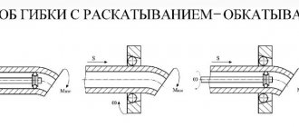
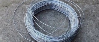
Fig. 1 How to cut a pipe at an angle of 45 degrees
45 degree cutting
Typically, in order to rotate a pipe by 45 degrees, fittings and bends with a rotation angle of 45 degrees are used, made of the same material as the pipes themselves; if the pipes are steel, then the turns are welded from steel. For HDPE pipes, there are electric-welded or cast bends at 45 degrees (note that it is almost impossible to find compression fittings with this angle of rotation in Russia).
But, if you still need to cut a round pipe made of steel or various types of plastics, then for this you will need a pattern for cutting pipes at an angle, the shape of which is calculated manually or by machine. The task is greatly simplified if it is necessary to cut a square metal profile at an angle of forty-five degrees.
For quick cutting, you can use a regular sheet of paper folded diagonally to mark the surface for future cutting. When using folded paper, proceed as follows:
- carry out on a straight surface of the profile in the place where the cut is made, strictly perpendicular to the line;
- apply a sheet of paper folded diagonally to the side surface with the sharp end to the line so that the upper edge of the paper triangle is flush with the top side of the metal profile.
Rice. 2 Homemade template for cutting pipes at 45 degrees
- draw a line with a pencil along the side of the sheet at an angle of 45 degrees, after which the paper corner is applied to the other side and traced with a pencil (it is better to use a thin marker).
For sawing, you can use a grinder with a metal disc, first drawing a thin line along the marking, and then gradually deepening it until the edges are completely separated.
When working with an angle grinder, the following factor must be taken into account: if the edges are completely cut, the disk may be damaged by a sharp corner, which will lead to its failure, and in the absence of protection on the angle grinder, even to injury to the worker. Therefore, it is advisable not to cut the corner edges to the end, but to leave a narrow groove and then break them off, subsequently grinding the protrusion.
Making a template for cutting metal profiles
If you need to cut a large number of pipes, you can make a template from a metal profile of a larger diameter using a paper sheet using the above method. The angle of inclination is checked with a protractor or a construction square - in this case, the two edges of the cut parts of the template are connected.
When working, a template is placed on the part to be cut in the right place and pressed tightly, the markings are applied with a sharply sharpened scriber while tracing the template outline. The part is cut in several passes with a gradual deepening of the groove.
Rice. 3 Cutting a metal profile using a miter box
DIY miter box for cutting pipes
Using a template is not very convenient - you have to make a cut along the line, holding the grinder in weight, which leads to large errors. If you have a welding machine, you can make a simple miter box - guides for the grinder disk, preventing it from moving to the side.
To do this, use a previously made template, drill a hole in the side of which and weld a nut. When working, a homemade miter box is placed on the profile, a bolt is screwed into its nut and the device is pressed against the profile surface. A grinder with a metal disc is used to make a cut, lightly pressing the disc against the side surface of the device. It is clear that with prolonged use, the edges in the miter box are gradually ground down, and although the process occurs simultaneously on all edges, some errors will appear over time. Therefore, it is better to make the device from hard, wear-resistant metal in order to increase its service life and obtain a more accurate instrument.
Application of thermal methods
In addition to mechanical methods, thermal methods of cutting pipes are also widely used. Here the tool is a gas cutter (propane or acetylene) or an electric arc welding machine. Even the thickest-walled, large-diameter pipes can be cut with a cutting torch. Productivity is also quite high. In addition, only these methods provide exceptional mobility - you can cut a pipe in a trench, basement, in places where a high-performance stationary machine simply cannot be dragged and connected.
It should be noted that thermal methods do not allow achieving high accuracy, and even cutting is not always possible. However, in a number of applications, such as operational repair of heating mains or main pipelines, it is not required. After thermal cutting, the resulting edges have to be additionally processed with mechanical tools, the cut line is leveled and the bevels are adjusted to the design values.
The thermal cutting method is also used when working with polymer pipe products. In thermal guillotines, the cut is carried out with an oblique thin cutter heated to a high temperature, sliding in guides.
The devices can also cut at an angle and very straight, but are only suitable for working with soft materials that have a low melting point.
90 degree cutting
To cut a round pipeline or metal profile of rectangular cross-section evenly across, use a sheet of plain paper. They wrap the workpiece so that the edges of the paper sheet coincide, after which it is fixed to the part using tape or glue. Using a grinder, a thin line is drawn near the edge of the paper sheet, after which it is gradually deepened until it is completely cut out.
A metal profile or round pipe can be cut using a template by placing an evenly cut element with a large internal diameter on it.
Collar insert
To obtain branches of metal pipeline lines in the form of tees, a collar insert is used, for which it is necessary to cut the edge of a round pipe adjacent to the walls of another at a right angle. To implement the method proceed as follows:
- cut the edges of the workpiece at right angles using the previously described method.
- On the round end surface, a marker marks four equidistant points located at angles of 90 and 180 degrees to each other.
- The size of the circle is measured, the resulting diameter is divided by 3. The resulting distance is plotted from two diametrically located points, after which these points are connected to two others by a smooth arc, drawing a line with a marker.
Fig.5 Example of a collar section of a pipe
- According to the markings, a cut is made with a grinder and semicircular segments are separated, after which the part is ready for welding. If there are minor inaccuracies in the mating, it can be compacted with a sledgehammer, placing it against the round surface of another element.
Techniques for cutting round pipes at an angle
Round pipes of different diameters are cut at an angle when changing the direction of the pipeline, but it should be taken into account that a straight cut at the desired angle, unlike a rectangular section, will not lead to a tight connection of the edges. Therefore, special patterns are used in which the marked edge has a curved shape, which makes it possible to obtain a high joint density.
Paper pattern for pipe
One of the common ways to make a pattern for pipes with a round surface is a method for which you will need a lined sheet of paper, a ruler and a pencil. To obtain a paper pattern proceed as follows:
- Draw a circle on a piece of paper with the diameter of the pipe being cut, divide the circle into 16 equal segments, each time dividing large segments into two equal ones.
Rice. 6 How to cut a pipe at 45 degrees - paper pattern
- Measure the length of the circle by multiplying its diameter by the number Pi equal to 3.14. Lay this dimension on both sides of the axis of the circle in equal segments, each of which is divided into 8 equal parts.
- Draw vertical lines upward from segments on a straight line and horizontal lines from points placed on the circle.
- The places where they intersect are connected by a smooth line and, as a result, a template is printed on paper, which is cut out and glued to the surface to be trimmed. For trimming, it is better to use a grinder with a disk of small diameter - the surface will be curved and when using a large disk, the error will increase.
Device for marking large diameter pipes
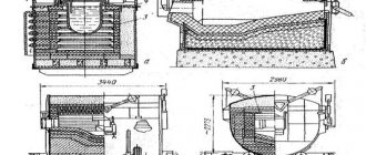
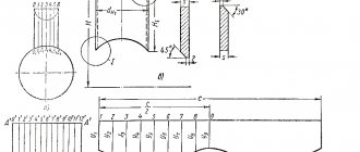
UNION OF SOVIET SOCIALIST REPUBLIC 9) I 1444 33/1 SANIE INVENTION ZMET STATE NOMITTEE OF THE USSR ON AFFAIRS OF INVENTIONS AND DISCOVERIES OF SECOND CERTIFICATES (56) Pipeline Pipemaker's Handbook on the preparation of bends, 1976, p. 76. (54) PRISP SPECIFICATION FOR LARGE DIAMETER PIPES(57) The invention relates to to mechanical engineering, and can be used for marking large diameter pipes before cutting.
The purpose of the invention is to improve the accuracy of marking. The device has a frame 1. with installation supports and centering supports 3, a U-shaped frame 6, a protractor with a dial 4, three blocks 9, 1 O and 11, a tension bolt 13, a thread 12 and a marking element in the form cord 15 stretched over cane 16. Frame 1 is installed on the pipe, frame 6 is placed under the pipe. The thread 12 of the armholes is launched through three blocks 9, 10 and 1 and is tensioned using a bolt 13. It forms a marking plane, which is established by moving the frame 1 and rotating the frame 6 to the required position relative to the pipe. Next, the trace of the plane is transferred to the pipe using a marking element, the cord of which is previously rubbed, for example, with chalk. The cord is pressed against the two sides of the triangle formed by thread 12 and the pipe. In this position, the reed 16 is led around the pipe until a complete trace is left. To ensure the possibility of marking pipes of various diameters, the transverse beam of the frame 1, installation supports, centering supports 3 and all sides of the 11-shaped frame 6 are sliding and have marking divisions. In order to facilitate the movement of the device along the pipe, the installation supports and centering supports 3 of the frame are equipped with rolling bodies, 3 z.p.f-ly, 2 il.vish5 10 15 20 25 30 35 40 45 50 55 In order to ensure the possibility marking pipes of various diameters, the transverse beam of the installation frame 1, the supports 2, the centering supports 3 and all sides of the C-shaped frame 6 are filled with sliding ones. For this purpose, the right side of the transverse beam of the frame 1, (Fig. 2) is a movable connection of the “pipe in rough” type. This unit consists of external The invention relates to mechanical engineering and can be used for marking large diameter pipes before cutting. The purpose of the invention is to increase accuracy markings, Figure 1: shows a device for marking large-diameter pipes, general view; Fig. 2 is a view of Ana Fig. 1. The device for marking large-diameter pipes contains a frame with mounting supports 2 and centering supports 3. On the frame 1, a protractor is mounted, consisting of a limb 4 and a reading window 5 on a U-shaped frame 6. The limb 4 is rigidly connected frame 1, and the frame 6 is connected movably by the frame 1 using axle shafts 7 so that its axis of rotation is located at the level of the working surfaces of the supports 2 of the frame 1 and is tangent to the upper part of the pipe 8 being marked. The C-shaped part of the frame 6 covers the pipe 8 from below. On the frame 1 and frame 6, three blocks 9, 10 and 11 are fixed. In this case, blocks 9 and 1 O are located on the inside of frame 1 in the places where the axle shafts 7 are attached. Block 11 is located in the middle of the lower part of the C-shaped frame 6. A strong thread 12 is stretched between these blocks. As a thread For example, steel cable, wire or fishing line can be used. Thread 12 Forms a triangular plane for marking pipe 8. Thread 12 is tensioned to the required elasticity by bolt 13. To transfer the marking plane formed by thread 12 to the surface of pipe 8, marking element 14 is used, which is a cord 15 stretched over a cane 16 in the form of a bow. Cord 15 is coated with a coloring agent, such as chalk or paint. pipe 17 and the inner pipe 18 included in it. To fix the relative position of these pipes, a clamping screw 19 is designed, screwed into a boss 20 welded to the outer pipe 17. To prevent pipes 17 and 18 from mutually rotating around their longitudinal axis, in the inner The pipe 18 is provided with a longitudinal groove 21, into which, when screwed, the tension screw 19 enters. In order to ensure that the size of the frame 1. is set to the required value corresponding to the diameter of the pipe 8 being marked, marking marks 22 are applied to the inner pipe 18. They can be marked, for example (on 2 not shown) 0.8, 1, 1.2 m, which will correspond to the diameter of the marked pipe 8. In order to ensure movement of the device along the pipe 8, the pores 2 and the centering supports 3 of the frame 1 are equipped with rolling bodies 23, for example balls. The device works as follows. According to the markings 22 using clamping screws 19 are installed in accordance with the diameter. of the marked pipe 8, the dimensions of the transverse beam of the frame 1, the centering supports 3, the supports 2 and the c-shaped frame 6. The device is installed on the pipe 8 so that the supports 2 of the frame 1 are placed along the longitudinal axis of the pipe 8, and the centering supports 3 touch its sides. Due to this, the entire structure of the device is located symmetrically relative to pipe 8. Thread 12 is passed through blocks 9, 10 and 11 around pipe 8. It is tensioned by bolt 13, thereby forming a triangular marking plane. The entire device, if necessary, with the help of rolling elements 23 moves along the pipe 8 so that the horizontal side of the thread 12 is aligned; square coincided with the starting marking point M. Then the H-shaped frame 6 is rotated along the limb 4 of the protractor. to the required angle (dotted image in Fig. 1), setting the triangle of the marking plane in a given position relative to the starting point M (Fig. 1) and the longitudinal base. would be 8.1444102 ABRI.Compiled by M. PhilTechred Ch, Didyk as rector M, Maksimishinets actor A. Dolin akaz 6432 1 Circulation 880 Subscribed by the USSR State Committee for Inventions and DiscoveriesMoscow, Zh., Raushskaya nab., 4/ VN 13035, physical enterprise, Uzhgorod, st. Design production To transfer the trace of the marking plane to the surface of a pipe of 8 sizes. the precise element 14 with its cord 15 is pressed against the two sides of the triangle 5 formed by the thread 12 and the surface of the pipe 8. In this position, the marking element 14 is drawn around the pipe 8 so that the cord 15 covered with a dye leaves a complete mark on the pipe 8. Pipe 8 is cut along the marked mark using, for example, an autogen. Formula 15 1, A device for marking large-diameter pipes, containing a marking element, differing in that, in order to increase marking accuracy, it is equipped with a frame with centering and mounting supports, three blocks, located in the same plane and obra-. forming a triangle, and a thread covering 25 of them to form a marking plane, and the marking element is made in the form of a cane and a cord stretched over the cane and covered with a dye, while the centering supports are located symmetrically relative to the installation supports, the blocks are fixed inside the frame, and the cord The marking element in the working position is placed tangentially to the two sides of the triangle of the marking plane.2. The device according to claim 1, characterized in that, in order to expand technological capabilities, the frame is made in the form of a body with a limb and a frame pivotally connected to it with a reading device corresponding to the limb, while centering and mounting supports, as well as two blocks are installed on the body, and the third block is installed on the frame.3. The device according to claims 1 and 2, characterized in that the body and frame of the frame are made sliding. 4. The device is characterized by the fact that, in order to improve service conditions, the centering and installation supports are equipped with rolling elements. Look
Tools used
There are several ways to cut a pipe; for this, construction and industrial tools for metal processing are used. Of all the types, only the grinder allows you to obtain curved surfaces without further processing with the closest arrangement of edges.
For individual use
The following tool is used for cutting steel pipes at home:
Manual pipe cutters. Allows you to cut round parts with an even, right angle of cut due to the cutting edges of the rollers. There are several varieties of products of this type, consisting of single rollers or a series of rollers attached to a chain. In everyday life, such devices are quite rare and are more suitable for professional work.
Precision cutting devices
Among branded devices that could be used in everyday life to make cuts at an angle, you can pay attention to Italian-made equipment.
The Mini Cut band saw is a small-sized device with manual clamping, for working not only with pipes, but also with angles, rods, and profile elements.
The machine supports setting the cutting angle from 0 to 45º. The procedure is carried out using a tape at a speed of 45 reciprocating movements per minute. The device is equipped with a 370 W electric motor, which is powered from a household network. The maximum permissible diameter of a round pipe to be cut is 65 mm.
On an industrial scale, numerous installations with electromechanical and electrical drives have been developed for pipe cutting. Technically sophisticated devices allow high-precision thermal, oxygen and plasma cutting:
How to cut a cast iron pipe
The main difference between cast iron and ordinary steel is its high fragility and large wall thickness; its precise cutting must be performed in the following sequence:
- The marking angle is drawn according to the template using a scriber, for
supports under the part are placed on a wooden board or board.
- Use a grinder to make a shallow cut of the surface around the entire perimeter.
- Next, the groove is deepened in several passes until the two parts are completely separated.
Welding technology
Gas, argon arc or electric arc welding without the use of edge bevels begins with adjusting the ends. The minimum gap between the pipes in this case is 0.5 mm, and the maximum is 1.5 mm. In addition, this technique can only be used with pipe wall thicknesses from 1 to 6 mm. The process must begin by tacking the corner joint with spot welds, then correct the location of the pipes and weld the joint from the outside along the entire diameter.
For angular mating with a one-sided end, it is assumed to produce a chamfer with an angle of 50°. And with a double-sided section, it is assumed that two chamfers are used, made at an angle of 30°. In the first option, the gap between the edges is 1-2 mm, and in the second – 2–5 mm. In other words, you practically don’t have to worry about the correct execution of the end surfaces. With this joining method, the pipe wall thickness ranges from 2 to 20 mm.
Some tips for cutting pipes
Sometimes households need to cut to connect a pipeline at different angles or along an axis. The main tool for performing these works is a universal grinder and metal discs.
Rice. 9 Pipeline slitting
Making a longitudinal cut
To make a high-quality, even longitudinal cut, you can use a simple device in the form of a metal corner. It is securely fixed to a flat wooden surface with screws and the pipe is pressed against it with a heavy weight. Using an angle grinder, make a longitudinal cut in the pipe top, lightly resting the disc on the surface of the angle.
The corner can be attached to the pipe with clamps and a slot can be made along the upper wall of the corner in a similar way.
Oblique cut
When changing the direction of the pipeline at an angle greater than 90 degrees, manual methods for making templates become too complex. Using a special program for calculating and creating patterns on a computer for any angles can come to the rescue. The good thing about this method is that it has high accuracy in creating paper templates and is easy to implement if you have a printer.
To obtain a paper pattern, the necessary data on bending angles and pipe diameter is entered into the program, after which a template is obtained, which is printed on a printer in full size. All that remains is to cut it out, stick it on the element to be cut and mark its outline.
Further cutting is done using a grinder in the standard way. An important advantage of machine templates is the ability to cut them in unlimited quantities with the same accuracy.
Rice. 10 Example of a calculation program
For high-quality connection of cylindrical pipeline elements, their precise cutting at angles of 45 and 90 degrees is required. To perform these works, special patterns are used, the shape of the bends of which is calculated manually or constructed by computer. They are cut out on paper and glued to the pipe surface, then the element is cut along the paper contour with a grinder with a small disk. Thus, it is possible to obtain a high-precision corner connection with the edges as close as possible.