We recommend purchasing:
Installations for automatic welding of longitudinal seams of shells - in stock!
High performance, convenience, ease of operation and reliability in operation.
Welding screens and protective curtains are in stock!
Radiation protection when welding and cutting. Big choice. Delivery throughout Russia!
General information
The surfaces of parts (both external and internal) are classified as shaped if they are formed by a curved generatrix, a combination of rectilinear generatrices located at different angles to the axis of the part, or a combination of curvilinear and rectilinear generatrices.
On lathes, shaped surfaces are obtained:
- manual or automatic transverse and longitudinal movement of the cutter feed relative to the workpiece with adjustment of the profile of the processed surface according to the template;
- shaped cutters, the profile of which corresponds to the profile of the processed part;
- using devices and copying devices that allow processing the surface of a given profile;
- by combining the methods listed above.
Shaped surfaces on long parts, the specified profile of which is obtained using a template, a copier and fixtures, are processed with pass-through cutters made of high-speed steel or carbide.
When processing fillets and grooves with a radius R < 20 mm on steel and cast iron parts, cutters are used, the cutting part of which is made according to the profile of the fillet or groove being processed.
To process fillets and grooves with a radius R >20 mm, the cutting part of the cutters is made with a rounding radius equal to (1.5… 2)R. In this case, both longitudinal and transverse movement of the caliper is used.
To increase the productivity of processing shaped surfaces of complex profiles, shaped cutters are used (Fig. 4.39). The width of shaped cutters does not exceed 60 mm and depends on the rigidity of the machine-device-tool-workpiece (WW) system and the radial cutting force.
Cutting modes
For tangential shaped models (in most cases prismatic), it is possible to process an object with several edges, on each side or several profile sections. In most cases, they are located at very different depth levels to ensure separate sequential processing. In order to process several objects according to a template, the tool is installed in one position and transverse and longitudinal feeds of the workpieces are performed. In this case, any point on the cutting edge begins and ends work at a wide variety of points, without continuing cutting beyond the boundaries of a given interval. Tangential cutters are also used with a rotary feed motion. Such models are suitable for thin workpieces and shallow profiles.
The best blood pressure monitor for the wrist in 2022 - TOP 8 rating of the best
Radial (radius) options (in most cases prismatic or round) are designed for rotational feed. The edge during processing with a shaped cutter of this type describes the surface to be worked radially. In this case, the feed movement for the edge intersects the axis of the object. This makes it possible to process with different depths and create curved shapes. Due to the large contact area, the equipment is subject to heavy loads. Moreover, when working with long objects of small cross-section, they may become deformed. In view of this, reduced modes are used.
Compared with radial models, they are suitable for working with stepped workpieces of lower rigidity due to the cutting of smaller sections and lower cutting forces.
For surfaces of rotation, the cutter performs a feed (usually translational, sometimes radial), and the workpiece performs a circular motion.
In addition to lathes, it is possible to use shaped cutters for planing, slotting and specialized for cylindrical objects. In these cases, radial design models with translational feed perpendicular to the axis of the part are used. For example, parts of gear shaping heads that work to work with cylindrical gears.
In the case of rotary feed, a tangential design is used. The edge of such models describes a surface of rotation, touching the object. In this case, any point on the edge at a certain moment removes a fragment of the workpiece and moves away from it.
The helical feed motion is used for workpieces of appropriate shape. In this case, the cutter does not cut at one level, but goes deeper after any pass. This is how threads are cut.
Machining with through cutters
With a small batch of workpieces and appropriate preparation of the worker, the shaped surface can be processed with a pass-through cutter with its simultaneous longitudinal and transverse movement, carried out manually.
When choosing a cutter, the shape of its tip and the location of the cutting edges should allow processing of a shaped surface with specified inclination angles and radii.
To acquire the skill of simultaneous longitudinal and transverse movement of a cutter along a given path, you should first (before processing a shaped part) perform several exercises, which will allow you to become familiar with the features of machine control during shaped processing. To do this, a finished part with a shaped surface of a complex profile is installed in the chuck or in the centers. When moving the caliper by coordinated rotation of its handles, make sure that the tip of the cutter moves in close proximity (with an equal gap of up to 1 mm) from the surface of the part.
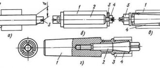
Having made sure that the machine control is reliable, they proceed to processing the part with a shaped surface. In Fig. 4.40, a shows the sequence of processing the shaped surface of the handle blank using the described method. The workpiece is secured in a three-jaw chuck using surface A (Fig. 4.40, b), and the tail part of the handle, consisting of surfaces B, C, D, and E, is processed with a through cutter. Having installed the handle in the chuck along surface G (Fig. 4.40, c), the shaped part of the handle is processed. Using a scale on the machine bed, markings are made (along the axis of the workpiece) of the largest and smallest diameters of the shaped surface of the handle, and then the rough allowance is removed using a passing cutter in several passes (see the shaded areas in Fig. 4.40, c).
The final removal of the allowance (Fig. 4.40, d) is performed in several passes. First, carefully remove the scallops by smoothly moving the cutter along the axis of the workpiece and reciprocating the transverse slide of the caliper. Then a template with the profile of the finished part is applied to the non-rotating workpiece, the largest and smallest diameters of the shaped surface are measured and the places from which allowance must be removed are determined. To facilitate working conditions and increase productivity, experienced workers use automatic longitudinal feed, manually moving only the transverse slide.
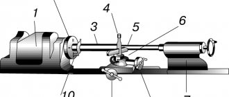
To increase the productivity and accuracy of processing shaped surfaces with a pass-through cutter, a copier is used (Fig. 4.41). The shaped surface of the handle 2 is processed with a cutter 7, the transverse movement of which is carried out along the copier 5 by finger 4 in accordance with its profile. Together with pin 4, rod 3 and the associated support with the cutting head move in the transverse direction. In this case, the cross feed movement screw is disengaged from the cross support nut, and the longitudinal feed movement can be carried out automatically.
Turning of workpiece surfaces
Turning
- technological process of cutting external, internal cylindrical, screw, conical and shaped, as well as flat end surfaces of bodies of rotation. Turning is carried out with turning tools on metal-cutting machines, both universal and special, including machines with computer numerical control (CNC). In addition, processing is performed on rotary and turret lathes, semi-automatic lathes, automatic machines and automatic lines.
The peculiarity of the technological processing process is that the cutting tool has one main blade. Throughout the entire cutting period, the cutter blade processes the workpiece under conditions of heavy loads and high temperatures.
When turning, there are two types of motion: rotational - around the axis of the workpiece, and translational - along its axis. Rotational movement
The workpiece is quantitatively characterized by the peripheral speed of the machined surface, called the cutting speed. Forward movement
along the workpiece axis imparted to the tool is the longitudinal feed motion. Both types of movement are carried out at a constant speed, and their combination gives the trajectory of the points of the cutter blade the appearance of a helical line. For each revolution of the workpiece, the blade of the turning cutter moves from position 1 to position 2 along its axis by the feed size s0 and removes one turn of the metal layer from it (Fig. 30.1). The width of the cut layer is determined by the cutting depth t.
The product of speed, feed and cutting depth is equal to the metal volume removal rate, which is a parameter for determining the efficiency of the cutting process. Cutting speed and feed
are the two most important parameters set by the operator in order to achieve optimal cutting conditions.
Depth of cut
is the thickness of the allowance to be removed, characterized by the distance between the machined and machined surfaces.
Typically, the cutting speed range is 0.005...3.5 m/s. The minimum feed value is 0.0125 mm/rev, and for very heavy cutting conditions - 2.5 mm/rev. The cutting depth can reach 25 mm or more.
A type of turning of workpieces is boring holes and processing end planes.
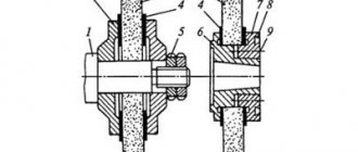
Boring is carried out according to the same principle as external turning. A feature of hole boring is a limited view of the cutting zone and low rigidity of the boring cutter. Under the influence of cutting forces, the tool bends and vibrates, which affects not only the size and roughness of the machined surface, but also the durability of the cutting tool.
To improve the accuracy of the holes made and the quality of the machined surfaces, instead of a cantilever-type boring cutter, it is preferable to use more rigid boring bars in which two cutters are fixed (Fig. 30.2). During the machining process, the boring machine imparts two types of motion to the mandrel: rotational - around its axis, and translational - along its axis. In this case, the peripheral rotation speed of the cutter tips is the cutting speed.
It is convenient to turn the end planes of workpieces using turning tools. In this case, machining can be carried out by moving the cutter both from the periphery to the center of rotation of the workpiece, and from the axis to the periphery.
Processing with shaped cutters
For processing fillets, threads and other shaped surfaces, shaped cutters are used. The profile of the cutting edge of shaped cutters completely coincides with the profile of the surface being processed, so the front surface of the cutter is installed exactly on the line of the centers of the machine. Shaped cutters are sharpened along the front surface. This must be taken into account when reinstalling the incisors. In the horizontal plane, the cutter must be installed perpendicular to the line of the centers of the machine; The correct installation is checked with a square, which is applied with one side to the cylindrical surface of the part, and the other to the side surface of the cutter, while there must be a uniform gap between the square and the cutter. The use of prismatic and round shaped cutters allows processing shaped surfaces with complex profiles.
Prismatic radial shaped cutters are mounted on a transverse support or in a turret with a horizontal axis of rotation. They are designed to work with cross feed motion. The cutting edge of the cutter must be installed in the center of the workpiece. Relief angles α are created by appropriate installation of the cutter in the holder, which is an advantage of this design.
Shaped round cutters with helical generatrices of the cutting edges provide lower roughness of the machined surface compared to round cutters with annular generatrices. Helical cutters are high-performance tools that are used on machines with turret heads.
The feed of the shaped cutter must be uniform and not exceed 0.05 mm/rev for a cutter width of 10...20 mm and 0.03 mm/rev for a cutter width of more than 20 mm. Feed depends on the rigidity of the part.
Classification of cutters for turning
The classification of turning tools is regulated by the requirements of the relevant GOST. According to the provisions of this document, cutters are classified into one of the following categories:
- one-piece tool made entirely of alloy steel. There are also cutters that are made entirely of tool steel, but they are used extremely rarely;
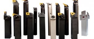
- cutters, onto the working part of which a plate made of hard alloy is soldered. Instruments of this type are most widespread;
- cutters with removable carbide plates, which are attached to their working head using special screws or clamps. Cutters of this type are used much less frequently compared to instruments of other categories.
Characteristic
A shaped cutter is a tool that, as is clear from its sound, is designed to process shaped surfaces. The possibility of working on open planes and in the process of preparing grooves is provided. You can easily make even a very complex profile if you have good equipment and professional skills
Important: such models are designed primarily for workpieces that differ greatly in length and width
It is allowed to use both pointed and backed teeth. In the second option, their general profile must be identical to the profile features of the workpiece, and therefore it is necessary to reduce the rake angle to zero. If it deviates from this value, auxiliary modification will be required (of course, carried out by professionals according to technological protocols). The main check and, if necessary, rejection is carried out before starting work using a special template.
The production of shaped cutters is fully regulated according to GOST 9305, which was adopted in 1993. The standard covers both convex and concave hardware and hardware intended for rounding corners. Standard size is from 50 to 160 mm.
Other information:
- the size of the keyways cannot deviate from the values prescribed in GOST 9472;
- Technologists take additional information about the external dimensions of cutters from standard 29116;
- it is preferable to use high-speed steel, but the alloy 9ХС alloy is also officially approved for use;
- The grade of steel used must be indicated on the end of the device.
Subtleties of the turning process
Separately, attention should be paid to turning shaped parts, when transverse and longitudinal feed is applied in parallel, carried out manually by the machine operator. This method of machining is used if it is necessary to produce a small batch of parts or the surface being processed is small in size. As for the first case, it is unprofitable to produce a conventional shaped cutter from an economic point of view, and to implement the second option, you may need a tool with non-standard dimensions, which causes difficulties in operation (for example, the formation of vibrations)
As for the first case, it is unprofitable to produce a conventional shaped cutter from an economic point of view, and to implement the second option, you may need a tool with non-standard dimensions, which causes difficulties in operation (for example, the formation of vibrations).
To remove the required layer of metal from the workpiece, either a finishing or a through cutter is used. The longitudinal slide moves to the left, and the transverse slide moves to the right and back. If it is necessary to process a surface characterized by small dimensions, then the longitudinal feed is realized by means of a support, which is installed in such a way that its guides are parallel to the center line of the equipment. Transverse feed in this case is carried out by the transverse slide of the caliper. The tool tip, regardless of the processing method, moves along a curve.
Processing parts with shaped surfaces is a rather complex task that requires certain skills and experience from the machine operator. Highly skilled turners prefer to use automatic longitudinal feed, while simultaneously performing cross feed manually. These processes can be fully automated using special copying devices. Their use is especially important when processing large batches of parts. Go to list of articles >>