If you want to know how much oxygen cylinders weigh, what types they come in, their volumes and sizes. You will find all this in our article, and also learn how to find out the amount of oxygen in a cylinder and the features of cylinder inspection.
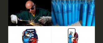
Oxygen is used in various fields of activity: construction, industry and medicine. Stored and transported in special oxygen vessels, the weight of which is a key parameter.
All characteristics of oxygen containers are usually written on the body of the product, where there is information about the weight of the tank in kilograms, a special trademark of the manufacturer, its own unique number, the number of further maintenance, maximum pressure and displacement.
OKP 14 1200
By Decree of the State Committee of Standards of the Council of Ministers of the USSR of December 19, 1973 N 2717, the introduction date was set from 01/01/75.
By Decree of the USSR State Standard dated August 14, 1991 N 1352, the validity period was lifted.
This standard applies to cylinders made of carbon and alloy steel, small volume - up to 12 liters and medium volume - from 20 to 50 liters with a working pressure of up to 19.6 MPa (200 kgf/cm2), made of seamless pipes and intended for storage and transportation of compressed, liquefied and dissolved gases at temperatures from minus 50 to plus 60°C.
The standard complies with the CMEA standardization recommendation PC 2496-70.
Pressure of oxygen or argon in a fully charged cylinder depending on temperature
To properly use gas in cylinders, it is worth knowing the pressure of its various types, indicating the temperature. For greater clarity, we have presented such data in the form of a table below.
| Pressure | Temperature |
| 105 kgf/cm2 | -40 °C |
| 120 kgf/cm2 | -20 °C |
| 135 kgf/cm2 | 0 °C |
| 150 kgf/cm2 (nominal) | +20 °C |
| 165 kgf/cm2 | +40 °C |
MAIN PARAMETERS AND DIMENSIONS
1.1. Cylinders must be manufactured for a working pressure of 9.8; 14.7; 19.6 MPa (100, 150 and 200 kgf/cm2) from carbon steel and for working pressure 14.7 and 19.6 MPa (150 and 200 kgf/cm2) from alloy steel.
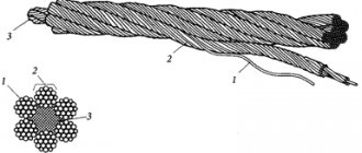
1.2. The main parameters and dimensions of the cylinders must correspond to those indicated in the drawing and table. 1.
Official publication Reissue (June 1992) with Changes N∙ ], 2. 3, 4, approved in October 1976, October 1980, February 1982, June 1986 (IUS 11-76.1-81, S-82.10-86).
© Standards Publishing House, 1974
© Standards Publishing House, 1992
Rice. 1 1 — support shoe; 2 — cylinder body; 3 — neck ring; 4 - valve; 5 - safety cap.
Dimensions in mm
Table 1
| Cylinder volume, l | Diameter of cylindrical part | Wall thickness of pressure cylinders, MPa (kgf/cm2), not less | Pressure cylinder body length, MPa (kgf/cm2) | Mass of cylinders for pressure MPa (kgf/cm2), kg | ||||||||||||
| carbon steel | alloy steel | carbon steel | alloy steel | carbon steel | alloy steel | |||||||||||
| 9.8 (100) | 14.7 (150) | 19.6 (200) | 14,7 (150) | 19.6 (200) | 9.8 (100) | 14.7 (150) | 19,6 (200) | 14,7 (150) | 19,6 (200) | 9,8 (100) | 14,7 (150) | 19.6 (200) | 14,7 (150) | 19.6 (200) | ||
| 0,4 | 70 | 1,6 | 2,2 | 2,9 | 1,0 | 1,9 | 165 | 170 | 175 | 165 | 165 | 0,6 | 0,8 | 1,0 | 0.6 | 0,7 |
| 0,7 | 255 | 260 | 270 | 255 | 255 | 0,9 | 1,2 | 1,5 | 0,9 | 1,0 | ||||||
| 1,0 | ,89 | 1,9 | 2,8 | 3,6 | 1,9 | 2,5 | 240 | 250 | 255 | 240 | 245 | 1,2 | 1,8 | 23 | 1.2 | 1,6 |
| 1,3 | 295 | 305 | 315 | 295 | 300 | 1,5 | 2,2 | 2,? | 1.5 | 1,9 | ||||||
| 2,0 | 425 | 440 | 455 | 425 | 435 | 2,1 | 3,1 | 4,0 | 2,1 | 2,7 | ||||||
| 2,0 | 108 | 2,4 | 3,4 | 4,4, | 2,4 | 3,0 | 320 | 330 | 340 | 320 | 325 | 2,5 | 3,7 | 4.7 | 2,5 | 3,1 |
| 3,0 | 445 | 460 | 480 | 445 | 455 | 3,4 | 5,0 | 6.4 | 3,4 | 4,3 | ||||||
| 3,0 | 140 | 3,1 | 4,4 | 5,7 | 3,1 | 3,9 | 310 | 325 | 335 | 310 | 320 | 4,1 | 6,0 | 7,9 | 4,1 | 5,3 |
| 4,0 | 385 | 400 | 415 | 385 | 395 | 5,0 | 7,3 | 9,6 | 5,0 | 6,5 | ||||||
| 5,0 | 460 | 475 | 495 | 460 | 470 | 5,8 | 8,5 | 11,4 | 5,8 | 7,6 | ||||||
| 6,0 | 535 | 555 | 575 | 535 | 550 | 6,7 | 9.8 | 13,1 | 6,7 | 8,8 | ||||||
| 7,0 | 610 | 630 | 660 | 610 | 625 | 7,6 | 11,1 | 14,9 | 7,6 | 9,9 | ||||||
| 8,0 | 140 | 3,1 | 4,4 | 5,7 | 3,1 | 3,9 | 680 | 710 | 740 | 680 | 700 | 8,5 | 12,4 | 16,6 | 8,5 | 11,1 |
| 10,0 | 830 | 865 | 900 | 830 | 850 | 10,2 | 15,0 | 20,1 | 10,2 | 13,4 | ||||||
| 12,0 | 975 | 1020 | 1060 | 975 | 1005 | 1,9 | 17,6 | 23,5 | 11,9 | 15,6 | ||||||
| 20,0 | 219 | 5,2 | 6,8 | 8,9 | 5,2 | 6,0 | 730 | 740 | 770 | 730 | 28,5 | 33,3 | 42,0 | 28,5 | ||
| 25,0 | 890 | 900 | 935 | 890 | 34,0 | 38.7 | 50,5 | 34,0 | ||||||||
| 32,0 | 1105 | 1120 | 1165 | 1105 | 42.0 | 47,7 | 62,5 | 42,0 | ||||||||
| 40,0 | 1350 | 1370 | 1430 | 1350 | 5i,5 | 58,5 | 76,5 | 51,5 | ||||||||
| 50,0 | 1660 | 1685 | 1755 | 1660 | 62.5 | 71,3 | 93,0 | 62,5 | ||||||||
Notes:
- 1. The weight of cylinders is indicated without valves, caps, rings and shoes and is a reference value and a nominal value for the manufacture of cylinders with a weight limit.
- 2. The lengths of the cylinders are indicated as reference and are accepted as nominal when manufacturing cylinders with a limited length.
- 3. The approximate weight of the metal cap is 1.8 kg; from fiberglass - 0.5 kg; rings - 0.3 kg, shoes - 5.2 kg.
1.1; 1.2. (Changed edition, Rev. N4).
1.3. Cylinders must be manufactured with normal and increased precision.
1.4.
Conventional precision cylinders are manufactured with a limited volume; cylinders of increased precision - by volume and outer diameter or by length and outer diameter. Maximum deviations should not exceed those indicated in the table. 2. Table 2
| Limit deviations | For standard precision cylinders | For high precision cylinders |
| By volume: | ||
| for small volume cylinders | +10% ‘ | . +5% |
| for medium volume cylinders | + 5% | +5% |
| By lenght: | ||
| for small volume cylinders | — | ?6 mm |
| for medium volume cylinders | — | ?15 mm |
| By outer diameter: | ||
| for carbon steel cylinders | — | ?1,5% |
| for alloy steel cylinders | — | ?2,0% |
Notes:
- 1. Maximum deviations in outer diameter for medium-volume cylinders made of carbon steel, which have been assigned the State Quality Mark, must not exceed ? 1.0%.
- 2. The curvature of medium-volume cylinders is no more than 0.5% of the length of the cylindrical part of the cylinder.
(Changed edition, Amendment No. 1, 3).
1.5. At the customer's request, alloy steel cylinders can be manufactured with weight restrictions. In this case, the mass of the cylinders should not exceed by more than 10% the mass indicated in the table. 1. Examples of symbols:
cylinder with a volume of 4 liters for a pressure of 14.7 MPa (150 kgf/cm2), made of carbon steel, standard manufacturing precision, for air:
- Air cylinder 4-150U GOST 949-73
the same, from alloy steel, increased manufacturing precision, with volume limitation, without weight limitation, for nitrogen:
- Nitrogen cylinder 4p-150L GOST 949-73
the same, with normal manufacturing precision, with mass restrictions, for air:
- Air cylinder 4-150 L-M GOST 949-73
the same, with increased manufacturing accuracy in terms of volume, with mass restrictions, for medical oxygen:
- Cylinder for medical oxygen 4P-150L-M GOST 949-73
the same, increased manufacturing precision, cylinder body length 400 mm, with weight limitation, for nitrogen:
- Nitrogen cylinder 4-150L-400-M GOST 949-73
the same, short volume 2 liters for a pressure of 14.7 MPa (150 kgf/cm2), made of carbon steel, increased manufacturing precision with a length limitation, without a weight limitation, for air:
- Cylinder for. air K2-150U-330 GOST 949-78 (Changed edition, Amendment No. 4).
Causes of gearbox failures
Like any technical device, the oxygen reducer is susceptible to problems that arise during operation. Thus, oxygen leakage may occur due to the fact that the seal between the valve and the chambers is broken. This may be because the hard rubber seat seal has worn out, or because foreign particles have entered the valve mechanism.
When operating in winter, the oxygen reducer may freeze. To prevent this phenomenon, the valve of the cylinder must be closed and blown with warm air. This will remove both ice and excess moisture. By the way, it is strictly prohibited to use fire to heat the gearbox.
There are frequent cases when the gearbox becomes clogged with foreign particles. To prevent this, the filter must be periodically blown or washed.
TECHNICAL REQUIREMENTS
2.1. Cylinders must be manufactured in accordance with the requirements of this standard and the “Rules for the design and safe operation of pressure vessels” approved by the USSR State Technical Supervision Authority according to working drawings approved in the prescribed manner. (Changed edition, Amendment No. 4).
2.la. Cylinders must be made from pipes that have undergone ultrasonic testing of metal continuity.
Note. The requirement of clause 2.1a is introduced from 01/01/89. (Introduced additionally, Amendment No. 4).
2.2.
The mechanical properties of the cylinder material must correspond to those indicated in the table. 3. Table 3
| Name of properties | Carbon steel | Alloy steel |
| Temporary resistance 6V, N/mm2 (kgf/mm2), not less | 638 (65) | 883 (90) |
| Yield strength Ov, N/mm2 (kgf/mm2), not less | 373 (38) | 687 (70) |
| Relative elongation bz, °/о, not less | 1.5 | 10 |
| Impact strength KCU, J/cm2 (kgf-m/cm2), not less, at 20°C | 29,4 (3) | 98,1 (10) |
(Changed edition, Amendment No. 4).
2.3. The materials of the cylinder valve bodies depending on the gas being filled, as well as the direction of the thread of the side fitting are indicated in the appendix. The side fittings of valves for toxic and flammable gases must be equipped with plugs. (Changed edition, Amendment No. 1, 4).
2.4. The outer and inner surfaces of the cylinders must be free of caps, holes, dulls, and cracks. Depressions, marks, traces of scale or tools, compacted and open wrinkles on the inner surface of the necks and bottoms and other minor defects should not be removed. wall thickness for the smallest values indicated in the table. 1. (Changed edition, Amendment No. 1).
2.5. The thread of the neck of the cylinders must be made in accordance with GOST 9909-81, in this case:
- the outer diameter of the thread in the plane of the end should be: for small volume cylinders - 19.2 mm, . for medium-volume cylinders - 27.8 mm,
- for medium volume cylinders (acetylene) - 30.3 mm;
2.6. At the request of consumers, cylinders can be manufactured with agreed dimensions of the outer diameter of the neck.
2.7. A steel ring must be securely fastened to the neck of cylinders with safety caps.
2.8. Rings and safety caps must be interchangeable.
2.9. In the threads of rings and caps, local minor tears and gouges with a length of no more than one third of the circumference are allowed on no more than one third of the total number of threads.
2.10. Shoes made from a section of steel pipe. must be tightly fitted onto the cylinders with a gap between the supporting plane of the shoe and the bottom of the cylinder of at least 10 mm.
2.11.
Valves of cylinders intended for liquid chlorine. must be equipped with a steel siphon tube, the length of which must correspond to that indicated in the table. 4. ' Table 4
| Cylinder volume, l | 20 | 25 | 32 | 40 | 50 |
| Tube length, mm, no more | 675 | 825 | 1045 | 1275 | 1575 |
2.12. Before screwing in valves or installing plugs in the necks, the inner surface of the cylinders must be cleaned of chips and loose scale. A thin remaining layer of oxides obtained during normalization, as well as individual stains caused by the method of cleaning the cylinders, are allowed. Small volume cylinders intended for medical oxygen, as well as on special orders from consumers, must be completely free of scale.
2.13. Cylinders for oxygen or hydrogen must be degreased, and those without valves must be additionally degreased at the customer’s site. Water and dirt are not allowed in the cylinders. .(Changed edition, Amendment No. 2).
2.14. Cylinders must be painted on the outside with oil, enamel or nitro paint. The marks must be clearly visible after painting. At the customer's request, the cylinders may not be painted.
2.15. Cylinders must be equipped with the following parts:
- a) small-volume cylinders with valves, and upon customer’s request, without valves;
- b) medium volume cylinders for acetylene - rings, caps and shoes;
- c) medium volume cylinders for ammonia, chlorine, phosphene, pseudobutylene, sulfur dioxide - valves, rings and caps;
- d) medium-volume cylinders, with the exception of cylinders specified in subparagraphs b and c, with valves, rings, caps and shoes.
It is allowed to complete cylinders with separate parts upon customer request.
Types of oxygen reducers
Gearboxes can be divided into two large classes – ramp and stationary. The former are distinguished by high gas throughput, reaching 120 cubic meters per hour. That is why they are installed to supply oxygen to combined welding stations. The second oxygen reducers are intended for personal use. They guarantee gas consumption ranging from 5 to 25 cubic meters per hour. It should be remembered that in appearance oxygen reducers are similar to each other.
GOST 13861-89 defines the following types of products for reducing oxygen pressure:
- On the cylinders - BKO, BKD and BPO.
- In the backbone network - SKO, SAO, SPO, SMO.
- Universal - U.
- Ramp ones - RKZ, RAD, RPD.
- Central action - CDC.
The key parameters of an oxygen reducing device are the ability to pass a certain volume of gas per unit of time and maintain a given gas pressure in the container.
Oxygen reducer BKO 50-4
Thus, BKO 50-4 provides a gas supply of 50 cubic meters per hour and with a pressure of 4 atm. BKO 50 – 12, at the same flow rate, maintains a pressure of 12 atm. By the way, devices of these models are most often used to equip working gas welding stations.
Oxygen reducer RKZ 500-2 (collection diagram)
RKZ 500-2 (ramp oxygen reducer) is designed for simultaneous supply of gas to several gas welding stations. These devices operate in a temperature range from -5 to +50 degrees Celsius. By the way, experts recommend equipping oxygen devices of this class with additional filters.
ACCEPTANCE RULES
3.1. Each cylinder must be subjected to smoke acceptance tests.
3.2. Cylinders are accepted in batches of up to 400 pcs. the same volume, size and the same heat treatment regime.
3.3. Acceptance tests include:
- test of endurance;
- leak test;
- tensile test;
- impact bending test;
- visual inspection;
- determination of mass;
- determination of volume.
3.4. The tensile test should be carried out on short longitudinal specimens. Samples in their calculation part should not be straightened.
3.5. The impact test shall be carried out on longitudinal specimens of type V. The axis of the notch shall be perpendicular to the wide edges of the specimen. Cylinders with a wall thickness of at least 5 mm are tested.
3.6. For tensile and impact bending tests, samples are cut from the bodies of finished cylinders or witness pipes, cut from the pipes from which a given batch of cylinders is made, and heat treated together with the cylinders of a given batch, and from alloy steel also from the same heat. For each test, at least two samples are taken from the lot. (Changed edition, Amendment No. 4).
3.7. If the test results do not comply with the requirements of this standard, tests are carried out on twice the number of samples. The results of the spot check apply to the entire lot. (Changed edition, Amendment No. 3).
3.8. Acetylene cylinders must be tested for leaks at factories that fill the cylinders with porous mass. (Introduced additionally, Amendment No. 3).
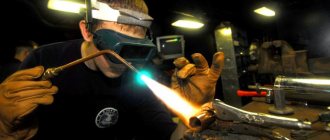
How to work with an oxygen reducer
When working with oxygen reducers, it is necessary to carry out several preparatory operations.
- Check the serviceability and integrity of the pressure sensors. The arrows must be set to zero and not change their position when turning the gearbox.
- Before connecting the gas supply hoses, it is necessary to check whether the operating screw that regulates the closing of the valve is turned out.
- After connecting the hoses, it is necessary to configure the device to supply the pressure necessary to perform the work.
Working with an oxygen reducer
In addition to the above operations, it is necessary to check the gearbox for leaks. To do this, the screw must be unscrewed completely.
Check the threaded connection for traces of oil and grease; if found, they must be removed immediately using a solvent.
By the way, you can check the tightness by applying soap foam to the threaded connections. If bubbles appear, work must be stopped and the gearbox must be sent in for repair.
4. TEST METHODS
4.1. Pneumatic and hydraulic pressure tests are carried out in accordance with the “Rules for the design and safe operation of pressure vessels.” Test duration is at least 1 minute. Pneumatic tests of cylinders intended for filling with gases, the penetrating ability of which is higher than that of air, must be carried out in accordance with regulatory and technical documentation. (Changed edition, Amendment No. 4).
4.2; 4.3. (Excluded, Amendment No. 4).
4.4. Cylinders equipped with a chlorine valve are tested with a pneumatic pressure equal to 2.94 (30 kgf/cm2).
4.5. Tensile test according to GOST 10006-80. The test speed up to the yield point and during its passage is no more than 10 mm/min, beyond the yield point is no more than 40 mm/min. It is allowed to control the mechanical properties of carbon steel cylinders using a non-destructive method according to the regulatory and technical documentation. In controversial cases, tests are carried out in accordance with GOST 10006-80.
4.6. Impact bending test - according to GOST 9454-78 on longitudinal samples of type 3.
4.7. If the test results do not comply with the requirements of this standard, tests are carried out on twice the number of samples. If the results of repeated tests are unsatisfactory, the entire batch of cylinders is sent a second time for heat treatment. No more than two repeated heat treatments are allowed. Additional tempering is not considered repeated heat treatment. (Changed edition, Amendment No. 4).
4.8. The volume of the cylinder must be controlled by limiting templates along the length; in this case, the volume of the cylinder should not be lower than the nominal one. The volume of two cylinders from a batch is checked by filling with water and determining the volume or mass of water.
Note. From 01/01/89, determination of the volume of all medium-volume cylinders is introduced. (Changed edition, Amendment No. 1, 2).
How much gas is in the cylinder?
The level of its consumption will directly depend on how much gas the cylinder contains. The amount of gas depends on the pressure inside the container and the type of contents.
In the case of supplies from our company, the distribution is as follows:
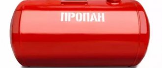
- Propane. 50 liter cylinders hold 10 cubic meters. m / 42 liters of liquid gas / 21 kg of liquid gas
- Acetylene. In a 40-liter cylinder with an indicator of 19 kgf/cm2 you will find 4.5 cubic meters. m / 5.5 kg of gas in a dissolved state.
- Carbon dioxide. The 40 liter capacity contains 12 cubic meters. m / 24 kg.
For gases such as helium, oxygen, argon, nitrogen, as well as for welding mixtures, which are supplied in 40-liter cylinders at a pressure of 150 atmospheres, the figure will be 6 cubic meters. m / helium 1 kg, and for other compressed gases - 8–10 kg.
LABELING, PACKAGING, TRANSPORTATION AND STORAGE
5.1. Cylinders are marked in accordance with the requirements of the “Rules for the Design and Safe Operation of Pressure Vessels”. Additionally, data on the type of heat treatment is applied:
- N - normalization;
- V - hardening and tempering.
Note. Until 01/01/89, the nominal volume of the cylinder is indicated.
5.2. The inscriptions on the cylinders and their painting are carried out in accordance with the “Rules for the design and safe operation of pressure vessels” and Table. 5.
5.3. Cylinders transported without valves must be protected from contamination with polyethylene or nylon plugs.
5.4.
Small volume cylinders are transported in containers made according to GOST 18477-79, without packaging. When shipped by carload in covered wagons, small-volume cylinders are transported packed in boxes in accordance with GOST 2991-85 (type III-1) with a cargo weight of no more than 200 kg or stacked up to the full capacity of the wagon. Dimensions of boxes according to regulatory and technical documentation in accordance with the requirements of GOST 21140-88; Medium-volume cylinders are transported without packaging. covered cars, gondola cars or containers manufactured in accordance with GOST 18477-79. It is allowed to transport cylinders in multi-turn packaging means in gondola cars or in packages in special cars. Table 5
| Name of gas | Coloring of cylinders | Inscription text | Lettering color | Stripe color |
| Nitrogen | Black | Nitrogen | Yellow | Brown |
| Ammonia | Yellow | Ammonia | Black | — |
| Argon raw | Black | Argon raw | White | White |
| Argon technical | Black | Argon technical | Blue | Blue |
| Argon pure | Gray | Argon pure | Green | Green |
| Acetylene | White | Acetylene | Red | — |
| Butane | Red | Butane | White | — |
| Butylene | Red | Butylene | Yellow | Black |
| Hydrogen | Dark green | Hydrogen | Red | — |
| Air | Black | Compressed air | White | — |
| Helium | Brown | Helium | White | — |
| Nitrous oxide | Gray | Nitrous oxide | Black | — |
| Oxygen | Blue | Oxygen | Black | -=- |
| Medical oxygen | Blue | Medical oxygen | Black | — |
| Oil and Gas | Gray | Oil and Gas | Red | — |
| Hydrogen sulfide | White | Hydrogen sulfide | Red | Red |
| Sulfur dioxide | Black | Sulfur dioxide | White | Yellow |
| Carbon dioxide | Black | Carbon dioxide | Yellow | — |
| Phosgene | Protective | — | — | Red |
| Freon | Aluminum or light gray | R (indicating its number) | Black | — |
| Chlorine | Protective | — | Green | |
| Cyclopropane | Orange | Cyclopropane | Black | — |
| Ethylene | Purple | Ethylene | Red | — |
| All other flammable gases | Red | Name of gas | White | — |
| All other non-flammable gases | Black | Name of gas | Yellow | — |
5.1; 5.2. (Changed edition, Amendment No. 4).
The arrangement and fastening of cylinders on vehicles must comply with the requirements of the “Technical conditions for loading and securing cargo” approved by the Ministry of Railways. (Changed edition, Amendment No. 4).
5.4a. Transport markings must be applied to one of the sides of each box, including main, additional and informational inscriptions in accordance with GOST 14192-77. (Introduced additionally, Amendment No. 4).
5.5. Cylinders are transported by all types of transport in accordance with the rules in force for each type.
5.6. Each batch of cylinders must be accompanied by a quality document certifying the cylinders’ compliance with the requirements of this standard, which must indicate:
- name of the manufacturer and its location (city or conventional address);
- product designation;
- number of cylinders and their numbers;
- results of hydraulic and pneumatic tests;
- designation of this standard.
5.5; 5.6. (Changed edition, Rev. N4).
5.7. Storage of cylinders according to group Zh2 GOST 15150-69.
5.8. Each cylinder that has been assigned the state Quality Mark in the prescribed manner and the certificate must be marked with an image of the state Quality Mark. in the manner established by Gosstandart. (Introduced additionally, Amendment No. 3).
Features of the selection of gas cylinders
Our company is engaged in the production and supply of gases and liquids. A wide range of products is available to customers. The product complies with GOST standards. Customers often contact us with similar questions about cylinders and their contents, so we decided to prepare for you this brief information with answers to the most common ones.
Our company is engaged in the production and supply of gases and liquids. A wide range of products is available to customers. The product complies with GOST standards. Customers often contact us with similar questions about cylinders and their contents, so we decided to prepare for you this brief information with answers to the most common ones.
MANUFACTURER'S WARRANTY
6.1. The manufacturer must ensure that the cylinders comply with the requirements of this standard provided that the consumer complies with the operating, transportation and storage conditions established by this standard.
6.2. The warranty period is 2 years from the date of putting the cylinders into operation. For medium-volume carbon steel cylinders that have been awarded the State Quality Mark - 4 years from the date of commissioning. (Changed edition, Amendment No. 1). Sec. 7. (Deleted, Amendment No. 4).
Oxygen reducer
The equipment used to reduce the oxygen pressure at the outlet of the storage vessel to the operating level and maintain it at the required level is called a reducer.
For each type of technical gas used in industry and everyday life, there are different equipment designs: for carbon dioxide one type, for acetylene another, for oxygen a third.
The key document defining the requirements for gas reducers is GOST 13861-89. This document defines the general conditions for products of this type.
CYLINDER VALVE CASE MATERIALS AND SIDE FITTING THREAD DIRECTION
Table 6
| Name of gases | Valve body material | Side fitting thread direction | Name of gases | Valve body material | Direction of Side Fitting |
| Nitrogen | Brass | Right | Methane | Brass | Left |
| Ammonia | Steel | Right | Propane and other flammable gases | Steel or brass | Left |
| Argon | Brass | Right | Sulfur dioxide | Steel | Right |
| Butane | Brass or steel | Left | Carbon dioxide | Brass | Right |
| Butylene | Brass | Left | Phosgene | Steel | Right |
| Hydrogen | Brass | Left | Freon | Steel or brass | Right |
| Air | Brass | Right | Chlorine | Steel | Right |
| Helium | Brass | Right | Chlormethyl-til | Brass | Left |
| Oxygen | Brass | Right | Chloroethyl | Brass | Left |
| Xenon | Brass | Right | Ethylene | Brass | Left |
Editor L. I. Nakhimova Technical editor O. N. Nikitina Proofreader V. I. Varentsova
Delivered to embankment 02.09.92 Sub. in the oven 16.10.92 Conditional p.l. 1.0. Conditional cr.-ott. 1.0. Uch.-ed. l. 0.83. Shooting gallery 1247 copies
Orders ■Badge of Honor■ Publishing house of standards, 123557, Moscow, GSP, Novopresnensky lane, 3 Type. ■Moscow printer■. Myskva, Lyalin lane, 6. Zak. 1462
Note. When ordering cylinders for gases not listed in the table, the customer must indicate the type of valve in the order.
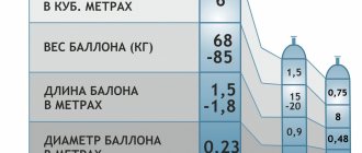
How much do the cylinders weigh?
The weight of a fully filled cylinder is often an important parameter when transporting it. Weight distribution is shown in the table below.
| Gas type | Volume | Empty weight |
| Argon, welding mixture, oxygen, carbon dioxide, helium, nitrogen | 40 l | 70 kg |
| Acetylene | 40 l | 90 kg |
| Propane | 50 l | 22 kg |