Parting and grooving: important to know
Parting and grooving is a separate branch of turning that combines a wide range of different operations that require specially designed tools that can sometimes be used for conventional turning. Below we will try to give useful recommendations for parting and grooving operations.
Edge height adjustment for trimming and grooving
- Position the cutter so that it is at a 90° angle to the workpiece. This ensures a high surface finish and reduces the risk of vibrations.
- Set the cutter to the center of the axis with a tolerance of ± 0.1 mm, especially when processing workpieces of small diameters. In this way, the longest tool life is achieved, cutting force and burr formation are reduced.
Segment
- Reducing the feed by 30% when the cutter approaches the middle of the workpiece extends the life of the insert.
- The cutter with the shortest overhang should be selected to prevent vibration and tool deflection.
Longitudinal turning, profiling
- Machining sequence 0.5 mm: radial feed to required depth of cut (max. 0.75 x insert edge width), radial retraction 0.1 mm, longitudinal turning to next stop, diagonal retraction outward 0.5 mm to initial points, radial feed to the required feed depth, etc.
- When grooving the base of a groove or chamfering, follow the instructions provided. This reduces tool deflection and prevents chipping of the cutting edge.
Face machining
Roughing
- Turning is carried out from the large ø to the axis. When retracting the cutter, it is recommended to slightly change its angle (1).
Grooving
- Depth of cut with axial feed is less than 0.75 x S (edge width). If the groove width is greater than the depth, follow the technological operations shown in the figure. If the groove depth is greater than the width, grooves (2) should be machined in separate operations to the required ø.
Finishing
- For finishing, you should first grind the outer ø base. Then you should grind the inner ø to the required size as shown in Figure (3).
Internal processing
- The processing procedure is as shown in the figure. When machining blind holes, for better chip flow, you should work from the inside out.
Recommended cutting conditions
| Plate size | Recommended feed (mm/rev) | |||
| Plate width | Segment | Grooving | Turning | Profiling |
| 2.5 | 0.05 — 0.15 | 0.05 — 0.15 | 0.05 — 0.15 | 0.05 — 0.15 |
| 3 | 0.05 — 0.15 | 0.05 — 0.15 | 0.07 — 0.15 | 0.1 — 0.2 |
| 4 | 0.05 — 0.2 | 0.05 — 0.2 | 0.07 — 0.25 | 0.1 — 0.2 |
| 5 | 0.07 — 0.2 | 0.07 — 0.22 | 0.1 — 0.25 | 0.15 — 0.3 |
| 6 | 0.1 — 0.3 | 0.07 — 0.25 | 0.1 — 0.3 | 0.15 — 0.3 |
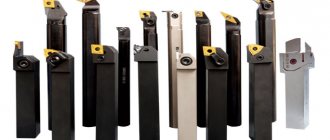
We also advise you to familiarize yourself with the range of tools for cutting and cutting grooves
External Grooving and Cutting
Home / Plumbing / Improving the skills of performing metalwork and turning works / Working on a lathe.
External Grooving and Cutting / External Grooving and Cutting March 6, 2012
The grooves are turned with slotted cutters. Narrow and imprecise grooves are turned with cutters in one pass.
| Grooving a groove in one pass |
The width and shape of the cutting edge of the cutter must correspond to the shape and dimensions of the groove. Grooves with precise dimensions in width and diameter are made with slotted cutters, the width of the cutting edge of which is narrower than the width of the groove.
Make a groove in three passes. First, an allowance is left along the width and diameter of the groove, then the left wall of the groove, the right wall and the diameter of the groove are finished turned.
| Leaving an allowance for the width and diameter of the groove |
| Grinding the left wall of the groove |
| Grinding the right wall of the groove and along the diameter |
Wide grooves are turned in several passes in the same way as grooves with precise dimensions. First, remove the allowance from the right side, and then from the left side of the groove walls. Remove the allowance from the walls by feeding the cutter transversely to the axis of the workpiece. The position of the right and left walls of the groove is determined using a measuring tool or template.
In mass production, wide grooves are machined using fixed longitudinal and transverse stops.
Longitudinal stops are installed on the frame guide to limit the movement of the caliper along the axis of the workpiece.
Installing the longitudinal stop
Longitudinal stops eliminate the need for the turner to mark a groove on each workpiece being processed.
Cross stops limit the movement of the cutter to the desired groove depth.
Shallow grooves are cut with groove or combined cutters.
| Grooved (a) and combined (b) cutters |
The parts are cut with cutting tools.
| Cutting the workpiece |
Cutting cutters have a long head and low strength. The strength of the cutter head is increased by increasing its height.
When cutting, vibrations occur, which lead to breakage of the cutter. Vibrations are combated by increasing the rigidity of the workpiece and cutter attachment. To do this, before cutting, tighten the support wedges and tighten the screw securing the carriage to the frame, which prevents the carriage from longitudinal displacement.
To reduce vibration, it is recommended to cut while the spindle is rotating in reverse, using a curved cutter, which is installed with the cutting edge down.
| Cutting a part with an inverted cutter |
Questions
- What kind of cutters are used to cut external grooves?
- Tell us about the techniques for turning wide grooves.
- What kind of cutters are used to cut shallow grooves?
- How to increase the rigidity of a cutting tool?
“Plumbing”, I.G. Spiridonov, G.P. Bufetov, V.G. Kopelevich
Modern methods of design and construction of country houses
Smart home system in a city apartment
Plasma cutting of metal
Iron casting
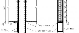
Purpose, types and requirements for grooves. Grooves are made on parts in order to ensure the exit of a threaded cutter or grinding wheel at the end of the working stroke, for installing springs, shift forks, belts, etc. They are radius, angular and rectangular in shape.Grooves can be machined on cylindrical surfaces, on ends and ledges.
When making grooves, it is necessary to maintain the dimensions, shape* location and cleanliness of processing in accordance with the technical requirements of the working drawing,
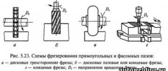
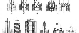
Grooving cutters and their installation on the machine. Various types and geometries of groove cutters are shown in 57.
The shape of the cutting edges of cutters for radius and angular grooves is carried out strictly according to the profile of the groove. During sharpening, they are controlled using templates in the light.
For rectangular groove cutters, a characteristic requirement is the straightness of the main cutting edge. For this purpose, such cutters for precision work are adjusted along the front and main rear surfaces.
The front surface of groove cutters is made flat, with a rake angle y equal to zero when turning radius and angular grooves (to avoid distortion of the groove shape) and with a positive angle y for cutters when processing rectangular grooves. In the latter case, approximate values of the front angle can be taken within the limits specified in § 7 of Chapter. I. The main rear surfaces are sharpened at an angle a = 8. The auxiliary rear angles are kept within 2-3°, and the lateral rear angles of the cutters for angular grooves are a2 = 5-6°. In cutters for face grooves, the rear auxiliary surfaces are made curved according to the shape of the sides of the grooves.
To reduce friction and distortion of the groove shape, the auxiliary cutting edges are positioned at an angle
Groove cutters are installed in height at the level of the axis of the centers of the machine with the smallest overhang from the tool holder and perpendicular to the surface of the part. The last condition especially applies to cutters for corner and rectangular grooves. The installation of the former is controlled by a template, which is applied to the machined surface of the part, and the cutter head is inserted into its angular groove. The cutters for rectangular grooves are brought until the main cutting edge touches the surface of the part and the correct installation in clearance is checked.
Grooving techniques. Grooves are made in one or several passes of the cutter, depending on their size.
Small grooves on a cylindrical surface are machined using a cross feed in one pass. To do this, the cutter is set at the required distance from the end using a ruler, caliper or along the longitudinal feed dial. In the latter case, it is brought into contact with the end of the rotating part, the dial is set to zero and the caliper is moved longitudinally to the required distance /. Then the cutter is brought to
touching the cylindrical surface, set the transverse feed dial to zero and move forward to grind the groove to its full depth.
Grooves at the end or shoulder are made using similar techniques, except that the cutter is set to the required diameter d along the transverse feed dial, and the depth of the groove is maintained along the longitudinal movement dial of the caliper.
Large corner grooves are processed in two steps: first, a rectangular groove is cut to its full depth, then the remaining metal is cut off from the sides with a profile cutter.
Wide rectangular grooves are machined in several passes of the cutter. To do this, during the first and subsequent preliminary passes, the groove is not cut to the full depth, leaving an allowance of 0.5-0.6 mm. During the last pass, the cutter is deepened to the full size of the groove and its bottom is cleaned with a longitudinal movement.
Cutting mode. When processing a groove, the cutting depth is taken to be its width, cut in one pass. The cutter feed is usually done manually and is within small limits - 0.1-0.2 mm/rev. The cutting speed is set slightly lower (15-20%) than during longitudinal turning.
Measurement and control of grooves. The accuracy of groove processing is determined using a ruler, caliper or templates.
Using a caliper, you can measure the width, depth, or diameter of the bottom of the groove, as well as its location along the length of the part.
When producing parts in large quantities, limit templates are used (60, c). Such templates have a pass and a non-pass side, which can be used to quickly and objectively determine the suitability of the groove.
Grooves of low accuracy are checked for clearance using one-sided templates (60, g).
When turning grooves, the following types of defects are possible: 1) inaccuracy of groove dimensions; 2) the location of the groove along the length of the part is not maintained; 3) the groove was of irregular shape; 4) insufficient purity of processing.
The first and second types of defects can arise due to the incorrect width of the cutter, incorrect setting of its size, or inaccuracy of readings on the dials.
An irregular groove shape is obtained when the cutter is not perpendicular to the surface being machined or when the profile is not accurately adjusted to the template.
Insufficient finishing may be the result of rough sharpening of the cutter, loose attachment of the workpiece and cutter, excessive feed, or working with a dull cutter.
Questions and tasks for review
1. Indicate the purpose, types and requirements for the accuracy of grooving.
2. Types of groove cutters.
3. Draw the geometry of the groove cutters and indicate the value of the sharpening angles.
4. How are groove cutters installed on the machine?
Explain techniques for cutting small grooves on a cylindrical surface. The same on the end surface.
6. How are large corner and rectangular grooves cut? Draw the sequence of processing.
7. What is taken as the depth of cut when turning grooves?
8. Specify the feed and cutting speed values for grooving.
d. What tools are used to measure and control grooves?
10. Indicate the types and reasons for groove defects.