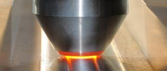
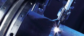
The best way to restore worn parts of parts in the form of a wheel rim, disk, and in general any bodies of rotation is vibration-arc surfacing. Which, in contrast to the oxygen gas and conventional arc welding methods, ensures uniform application of the welded/surfaced metal to the repair object.
The principle of the device for applying a uniform coating of metal is simple. This is the combination of a rotating part fixed on the shaft of a lathe with the free zone required for this part and a vibrating-electric-arc nozzle, or surfacing head, which is placed in place of the standard support of the machine or mounted on it.
Vibro-electric arc nozzle
This simple device is a mechanical vibrator or a special electromagnetic installation that operates on the principle of a solenoid in a relay, when the supplied alternating current oscillates a metal rod-electrode back and forth inside the winding.
Mechanical type vibrators are only called that, in fact they are also associated with the frequency of alternating current, and are essentially electromechanical. For both electromagnetic and mechanical vibrators, the oscillation frequency of the deposited wire, or electrode rod, can be in the range of 50-100 Hz.
Movements of the rod in the winding cause it to briefly touch the welded part, and then break away from it. When the electrode rod touches a part clamped and rotating in the machine, a short circuit occurs, the voltage becomes zero, and the current, on the contrary, increases abruptly. During separation, a voltage surge occurs, the current is interrupted, and an arc occurs between the part and the electrode. Since an inductor is included in the circuit, the constant voltage in the circuit is not enough for a constant discharge arc, but a pulsed supply of current and voltage can cause such an arc, which looks like a series of short flashes merging to the eye, which look like a continuous arc, but in fact it is not not being.
Structurally, the electric arc nozzle is part of a complex that includes a welding current source and a VDG-5 surfacing head (or its analogues). The main thing is that there is no need to use any homemade devices; the industry has long mastered different types of such attachments for lathes - with different attachment points and with different methods of feeding the wire from which the surfacing layer is formed.
The vibrating arc head also includes as integral parts
- Feed rollers from standard coils of wire of different types.
- Support nodes.
- A vibrator with a motor that vibrates the electrode.
- The tip ensures the supply of the electrode to the workpiece.
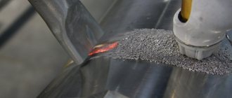
Van-arc welding
To connect small cross-section parts of rectangular and cylindrical shapes and, in particular, for welding reinforced concrete reinforcement, vane-arc welding, which is a type of arc welding, is used. The source of heat in bath-arc welding is the arc burning between the coated electrode and the metal bath. The seam has a short length, and the process is carried out continuously, resulting in the formation of a metal bath of significant volume. Melting of the edges of the metal being welded in this case is achieved not only due to the direct action of the welding arc, but also due to the heat generated by the metal bath.
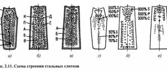
To hold the liquid metal, the remaining steel or removable ceramic and copper lining-forms are used (Fig. 3-9, a> b), covering the joint on three sides. The supply of the electrode as it melts into the arc zone is carried out manually or semi-automatically. Under certain conditions, the arc process can transform into an electroslag process. The source of heat in this case is a metal or slag bath (formed by melting the coating of the electrodes). Depending on the number of electrodes, a distinction is made between single-electrode and multi-electrode (two electrodes, beam, comb) vane-arc welding. Multi-electrode welding can be carried out from single-phase or three-phase power sources.
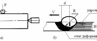
How does vibration arc surfacing occur?
It must be borne in mind that the efficiency of this process is very low. This occurs because at a conventional frequency of the vibrator current of 50 Hz, the contact of the electrode with the part is 0.01 seconds. That is, 65% of the process time is spent idling. But without the idle phase, full surfacing will also not be possible. To understand why this happens, you need to consider the process in fractions of a second.
- During the period of contact between the workpiece and the electrode at the point of contact, the current increases to 400 A per square meter. millimeter, and the wire electrode at the point of contact from a huge temperature jump heats up to critical states..
- The vibrator tears the electrode off the workpiece, and part of the electrode remains on it.
- The resulting arc melts this drop.
- The electrode, under the influence of a residual impulse in the winding, continues to move away from the welded part, the distance increases, the current drops to zero and the arc goes out. The idle phase begins.
All this happens from 50 to 100 times per second, and it is in the alternation of idling and touching with an arc between them that metal is deposited onto the worn workpiece.
The inductance introduced into the arc circuit serves as a source of energy accumulation during the open state of the electrical circuit. It causes a phase shift in voltage and current, so the passage of the current through the zero phase contributes to the emergence of a self-inductive emf, coinciding in direction with the voltage of the rectified network. This contributes to the re-occurrence of the arc after a circuit break and its stable combustion in a short period of time between touching and idling.
Electrodes for vibro-arc surfacing have a thickness of 1.5-2 mm, and are, in fact, wire made of steel of a certain grade, which to one degree or another coincides with the steel grade of the part being repaired. After a short circuit and separation as a result of an impulse in the winding, part of this wire remains on the part in a molten state.
Remaining (ironization)
Electrolytic deposition of iron can be carried out in baths with hot and cold electrolytes (hot and cold cooling) at direct and alternating asymmetric current. The forms of direct and alternating asymmetric current are shown in Fig. 26.
Rice. 26. Current forms used when steeling (ironizing) parts:
a - at constant current; b - with alternating (asymmetric) current
Rice. 27. Scheme of a complex anode for deposition of electrolytic iron (stagnation):
1 — electrolyte supply fitting; 2, 5 — anode half-rings; 3, 7 — electrical contacts; 4 - shaft journal; 6 — textolite anode body; 8 — lock; 9 - gasket; 10 - cavity filled with electrolyte
Cold plating with asymmetrical current is the process of applying metal coating to worn surfaces of parts using a controlled asymmetrical current. This type of cooling produces the most durable coating.
The pressure electrolysis process increases the hardness of the deposited electrolytic iron from HRC 45-48 to 60-63 with a significant improvement in coating quality.
Metal deposition onto a round part in a flow electrolyte under a pressure of 0.15–0.20 MPa is carried out inside the complex anode shown in Fig. 27.
Cold cooling is carried out in an electrolyte of the following composition: ferric chloride - 400-500 g/l; potassium iodide - 5-10 g/l; sulfuric acid - 1 ml/l; The hydrochloric acid content is determined by pH density, which should be no more than 1.5.
Additional technical conditions
To avoid overheating of the workpiece being repaired and, as a consequence, its deformation, the surface to be deposited is cooled with the following compounds:
- 10-20% solution of technical glycerin,
- 3-4% aqueous solution of soda ash.
There may also be cooling by cold air flows.
Restoring parts worn out as a result of long-term use has a completely justified economic rationale. The fact is that they usually restore old, irreplaceable parts of products (most often rotation shafts with unique characteristics), which have long been discontinued and are not available as spare parts.
Cooling parts with solutions or a directed air jet in these conditions seems not only justified, but also an urgently necessary measure to protect the surface of products from deformation and protect their dimensions.
The point of supply of cooling solutions should not coincide with the place where the arc burns, otherwise the quality of the deposition may suffer. To do this, simultaneously with the vibrators, a line through which cooling is supplied is installed, with adjusting mechanisms for supplying a glycerin or water mixture, or an air valve. But the cooling solution has another function - protecting the welded metal from nitriding processes, which will make it excessively brittle, and oxygen oxidation.
Chrome plating
A diagram of the electrolytic restoration of parts by chrome plating is shown in Fig. 23.
When chrome plating, the part is the cathode, and insoluble lead plates (half rings) are used as anodes.
In the auto repair industry, baths with a universal electrolyte are used for chrome plating.
The composition of the universal electrolyte for chrome plating includes chromic anhydride Cr2O3 (250 g/l) and sulfuric acid H2SO4 (2.5 g/l).
Rice. 23. Scheme of electrolytic restoration of parts by chrome plating:
1 - cathode electrical bus; 2 - outer wall of the bath; 3 - water for heating the electrolyte in the bath; 4 - inner wall of the bath; 5 — cathode [detail (—)]; 6 - electrolyte; 7 — electric heater; 8 - anode [lead plate (+)]; 9 — part suspension; 10 - anode electrical bus (+); 22 - bath cover
The 250:2.5 ratio, equal to 100, ensures a constant ion concentration. This ratio is maintained automatically when strontium sulfate SrSO4 and potassium silicofluoride K2SiF6 are introduced into electrolytes instead of sulfuric acid in quantities exceeding their solubility. Such an electrolyte is called self-regulating, since the concentration of SO^2-^4 and SiF^2-^6 ions is automatically maintained.
Chrome plating restores a large number of various, especially small-sized, parts with slight wear, valves and pushers, kingpins, shaft journals for bearings, etc.
The technological process of restoring parts by chrome plating includes the following operations:
- mechanical processing of the surface of the part until the required geometric shape is obtained;
- washing parts in organic solvents (gasoline, trichloroethane, etc.);
- mounting the part on the suspension in such a way that the parts are firmly held on it and equally located from the anode surface;
- electrolytic degreasing in a solution of the following composition: caustic soda NaOH—30—50 g/l; soda ash Na2CO3 - 25-30 g/l; liquid glass Na2SiO3—10—20 g/l; electrolyte temperature 60...70 °C; electric current density 5-6*102 A/cm2; holding time on the cathode is 2-3 minutes, on the anode - 1-2 minutes;
- washing in hot water (60...80°C);
- rinsing in cold water;
- loading parts into the chrome plating bath.
A general view of the installation for electrolytic deposition of metal is shown in Fig. 24.
Rice. 24. Installation for electrolytic deposition of metals OG-1349A:
1, 2 — baths with electrolyte; 3 - rheostat; 4 — control panel; 5, 13 — packet switch for polarity change; 6, 12 — switches for electric heating of baths; 7, 11 - ammeters; 8 - ammeter switch from 200 to 20 A; 9 - batch switch for installation in the electric current circuit from the rectifier; 10 - voltmeter; 14 — resistance store switches; 15 - installation table
Picking is the removal of the thinnest oxide film from a part within 30–90 s at a current density of (2.5–4.0) 102 A/cm2 by passing current in the opposite direction to the chromium deposition process.
Chrome plating of parts is carried out according to the selected mode. The hardness of chromium deposits depends on the current density and temperature of the electrolyte. To determine the current density and temperature of the electrolyte, use the graph shown in Fig. 25. In accordance with the schedule, the hardness and type of sediment (gray, shiny or milky) are set and the current density and temperature of the electrolyte are determined.
Rice. 25. Diagram of the dependence of the location of zones of various chromium deposits on the temperature of the electrolyte in the bath and current density:
1 - curves limiting the zone of formation of shiny deposits in a bath with a universal electrolyte; 2 - curve limiting the zone of formation of shiny deposits in a bath with a self-regulating electrolyte; 3 - zone of formation of wear-resistant deposits (numbers in circles show the microhardness of the deposited chromium coating)
The current density determines the strength required for electrolysis. It is installed using rheostats of the galvanic installation shown in Fig. 24, and is controlled by ammeter readings. The temperature is achieved by turning on the electric bath heater. The amount of chromium deposit depends on the time of chromium deposition.
After chrome plating is completed, the parts are removed from the bath, washed in running water, removed from the hangers and subjected to thermal and mechanical treatment.
Process stability
The stability and absence of technological failures in the surfacing process will be indicated by the uniformity of the characteristic crackling sound at the time of welding and the ammeter reading. Since the frequency of current and voltage fluctuations per second is equal to 50-100 Hz, the needle of an analog device will not have time to oscillate back and forth and will simply stand still - but this will precisely indicate the stability of the process.
If the melting of the wire electrode is accompanied by an unpleasant and uneven crackling sound with different frequencies and periodicities, and the ammeter needle makes random fluctuations, this indicates uneven application of the metal to the workpiece, in which cavities can form, and the layer will be nervous and loose.
What does the thickness of the layer depend on?
The thickness of the metal layer deposited on the part is influenced by two parameters:
- Workpiece rotation speed (peripheral speed, depending on the diameter of the shaft, wheel, rim of the part being repaired that is fixed to the machine shaft)
- Feed speed of welding wire electrode.
Increasing the rotation speed will result in a narrow and thin bead with a slow rate of metal growth. On the contrary, a decrease in the rotation rate with a simultaneous increase in the number and strength of vibrations of the wire, the surface being deposited will quickly increase in diameter. But to increase the thickness of the metal layer being built up, a thicker wire is also needed.
They try to avoid increasing the speed of rotation of the workpiece in every possible way and usually set the minimum possible speed - otherwise the appearance of cavities in the growing layer is inevitable. And the faster the part rotates, the more cavities will form.
Porous, low-quality surfacing metal also results when the part is contaminated with oils and greases.
Preparing parts
The surface to be deposited must be cleaned to a metallic shine.
Cleaning is done immediately before surfacing using sandpaper at the same speeds of rotation of the part as during surfacing. The runout of the surface being deposited should not exceed 0.5 mm. If the part is more bent, it must be straightened or processed on a machine before surfacing. Before surfacing, damaged threaded holes must be processed until the old thread is completely removed.
Consumables for metal extension
This is primarily a wire for surfacing. There are two main types of it:
- SV-15 for surfacing metal on cast iron products (gives the surface a special hardness with a certain fragility)
- Sv-08A Sv-18KhGSA, Np-50 (65G), Np-30KhGSA - for surfacing steel layers.
- Spring wire according to GOST 9389–75.
Welding with lying and inclined electrodes
IN
Recently, long-known, but previously little used methods of welding with inclined (gravity welding, Fig. 3-10) and lying electrode have found quite wide application. Interest in these methods is due to improved equipment and improved quality of electrodes. This allows one worker to service three to four stations, which provides increased productivity even compared to semi-automatic welding.
Electrodes used for lying electrode welding consist of an inner rod, a coating layer applied to it and an outer shell of a round or other shape with a longitudinal groove. The presence of a hole leads to concentration of the arc on the surface of the electrode opposite to it and stabilization of the welding process. Current is supplied to the inner rod and the outer shell. When welding with inclined and lying electrodes, good seam formation is ensured.