During various switching processes using electromagnetic starters, relays, contactors and other equipment, the electrical resistance in the switching element changes. In these devices, this function is performed by the gap between the contacts. In the closed state, the resistance becomes very small, and as the contacts open, it begins to increase.
Such changes occur very quickly, in an abrupt manner, and are accompanied by a chain break. In some cases, it is necessary to avoid such a break, so non-contact devices are used in such switching circuits. A typical representative of this group is a thyristor contactor, which includes thyristors that have a nonlinear electrical resistance that can change upward or downward.
Operating principle of a thyristor contactor
The operation of a thyristor contactor is based on contactless switching. This physical phenomenon consists in the changing conductivity of semiconductors connected to the circuit along with the load. During operation, there are no visible breaks in the circuit, and the process itself is as follows: when the circuit is turned off, the conductivity of the semiconductor decreases sharply, and the resistance can reach several tens of megohms. After switching on, the conductivity of the element is restored, and the resistance tends to zero and is measured in milliOhms (mOhm).
Semiconductor devices are various types of triacs, thyristors and transistors, connected in series with the load in an electrical circuit. Their action is based on the phenomenon of electron-hole transition (p-p), providing one-way conductivity from the anode (p) to the cathode (p).
The same principles apply to the operation of a thyristor contactor or AC switch. The most commonly used circuits are those with back-to-back connections of thyristors VS1 and VS2, marked in the figure. Pulses are generated by the control unit when the voltage passes through the zero mark. Under the influence of pulses, the thyristors open one by one, due to their shift between themselves by 180 degrees. As a result, a sinusoidal alternating current begins to move in the circuit. When the instantaneous value of the load current decreases, the thyristors turn off.
Thyristor switches
Thyristors are mainly used for switching AC power circuits.
They are capable of passing large currents with a low voltage drop; they are turned on relatively simply by applying a low-power control pulse to the control electrode. At the same time, their main disadvantage - the difficulty of turning off - does not play a role in alternating current circuits, since the alternating current necessarily passes through zero twice per period, which ensures automatic shutdown of the thyristor. The diagram of a single-phase thyristor switching element is shown in Fig. 9.1.9. Control pulses are generated from the anode voltages of the thyristors. If at the anode of the thyristor VS1
positive half-wave voltage, then when contact
K
, a current pulse controlling thyristor
VS1
through diode
VD1
and resistor
R. As a result, the thyristor
VS1
will turn on, the anode voltage will drop to almost zero, the control signal will disappear, but the thyristor will remain in a conducting state until the end of the half-cycle, until the anode current passes through zero.
In another half-cycle, with the opposite polarity of the network voltage, thyristor VS2 is turned on in a similar way.
As long as contact
K
is closed, the thyristors will automatically turn on one by one, ensuring the passage of current from the source to the load.
Contactors (starters). Thyristor elements (Fig. 9.1.9) are the basis of single-phase and three-phase contactors. In Fig. 9.1.10 shows, as an example, a diagram of a reversing starter for asynchronous motors. The power switching elements are thyristors VS1 - VS10,
which are opened by contacts
K11, K12, K13
of relay
K1
(forward) or contacts
K21, K22, K23
of relay
K2
(backward).
Current transformers TA1
and
TA2
send an overload signal to the
BZ protection unit,
which, acting on the base of the transistor
VT,
removes power from relays
K1
and
K2
and thereby turns off the starter.
Thyristor control stations for asynchronous unregulated electric drives with a power of up to 100 kW of the TSU type are designed in a similar way. The stations perform the operations of starting, stopping, dynamic braking and engine reverse.
The use of thyristors as contactless DC devices is difficult due to the shutdown problem. If in chains
While alternating current thyristors turn on automatically when the current passes through zero, in direct current circuits it is necessary to use special measures to forcibly reduce the thyristor current to zero, i.e., perform the so-called forced switching of the thyristor current. There are many different forced switching schemes. Most of them contain switching capacitors, which at the right moment, with the help of auxiliary thyristors, are introduced into the circuit of the main thyristor and turn on
his.
Rice. 9.1.9. Diagram of a single-phase thyristor switching element
In Fig. Figure 9.1.11 shows one of the forced switching schemes. When a control pulse is applied to the power thyristor VS
the load circuit
R
n is turned on (the current through the thyristor
i
T is equal to the sum of the load currents
i
N and through the capacitor
i
C), the switching capacitor
C
is charged to the source voltage
U.
The polarity of the voltage
c is
indicated in Fig.
9.1.11, a
.
The circuit is ready to turn off, and if at time t
1 a control pulse is applied to the auxiliary thyristor
VSB,
then capacitor C will turn on
Rice. 9.1.10. Irreversible starter circuit
parallel to thyristor VS,
the load current will move from the thyristor
VS
to the capacitor
C
and the thyristor
VS
will turn off.
Under the influence of the source EMF, the capacitor will be recharged. The capacitor voltage ic
will change during recharging from -
U
to
+ U
(Fig. 9.1.11,
b
), and the current
ic
will gradually drop to zero.
Load Rн
will be disconnected from the source.
If now again at time t2
you turn on the load
Rн
, opening the thyristor
VS,
then again the capacitor
C
will be charged to voltage -
U
and the circuit will be ready to turn off again.
Thus, turning off a thyristor on direct current is more difficult than on alternating current. This problem will be finally resolved only after
Rice. 9.1.11. DC thyristor switch circuit ( a
) and a diagram of its work (
b
)
Rice. 9.1.12. Contactless switch diagram Fig. 9.1.13. Oscillogram of short circuit current interruption
creating powerful, fully controllable thyristors, capable of being locked when exposed only to the control circuit.
Automatic switches. Based on thyristor elements (see Fig. 9.1.9), automatic contactless switches of the BA81 series are made for currents up to 1000 A. They are designed to protect electrical installations in networks with a voltage of 380/660 V AC with a frequency of 50 - 60 Hz during overloads and short circuits , as well as for switching with different switching frequencies. These switches use forced switching off of thyristors using a forced switching circuit (Fig.
9.1.12). Main thyristor VS1
series T-160 is controlled by pulses from a high-frequency generator (not shown in the figure).
Thyristor VS1
is turned off by discharging capacitor C through the switching thyristor
VS2.
The latter is turned on from the voltage of the switching capacitor
C
through a low-power thyristor
VS3,
which reduces the power of the control circuit. Capacitor C
charged from the mains voltage through a transformer and diode
VD1.
Each switch consists of three power blocks with back-to-back main thyristors connected in parallel.
Thanks to the use of forced switching of thyristors, protection against short circuits is carried out with current limitation during the shutdown process. In Fig. Figure 9.1.13 shows an oscillogram of short-circuit current shutdown by a thyristor switch. Curve 1
shows the increase in short-circuit current in the absence of protection, and curve 2 shows when the thyristor switch is turned off by a forced switching circuit. As can be seen from the figure, in this case, the increase in short-circuit current is interrupted and the maximum current imax is no more than 0.02 - 0.05 of the short-circuit shock current.
Output devices (intermediate relays). Schemes in Fig. 9.1.9 are widely used as switching devices for control circuits of executive devices (starters, contactors, electromagnets, couplings, etc.). An example is contactless output devices of the UVB-11 type, which are designed to amplify the output command signals of logical devices and switch AC and DC load circuits. They are designed for switching AC circuits up to 6 A and voltage up to 380 V, DC circuits up to 4 A and 220 V.
In Fig. Figure 9.1.14 shows the circuit of the UVB-11-19-3721 amplifier, intended for switching alternating current circuits. VS is used as a switching element
type TS2-25, shunted by varistor
R
for protection.
from overvoltage. The triac is turned on by connecting its control electrode to one of the power terminals using the contact of a reed relay K.
This relay simultaneously provides galvanic isolation of the input and output circuits. Switching off the seimistor
Rice.
Thyristor DC contactors
DC contactors have a number of individual features and characteristics. One of them is the ability to work with much higher switching frequencies during adjustments and conversions of current and voltage. In this they differ markedly from thyristor regulators that provide stabilization in circuits with alternating current. DC devices provide a higher level of performance, and this factor largely determines the scope of their use.
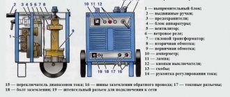
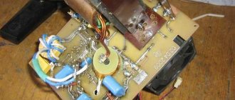
Thyristor starter, assemble a starter from T161 thyristors
9.1.14. Amplifier UVB-11-19-3721: a -
symbol;
b
- functional diagram
with contact K
occurs spontaneously at the first transition of the load current through zero.
In order for the circuit to be controlled by logical signals from other elements, a matching stage is provided on an IC of type K511LI1, the output of which is connected to the winding of the reed relay K.
In amplifiers intended for switching load circuits
DC, this switching is carried out by a thyristor, which is turned off using a forced switching circuit, i.e., by discharging a pre-charged capacitor onto the thyristor.
LECTURE No. 30
9.2. Microprocessors and electronic control machines
9.2.1. General information.
9.2.2. Functional diagram of a computer.
9.2.3. Electronic and microprocessor devices, their classification and
physical phenomena in them.
9.2.4. Functional diagram of DC motor control
current using a microprocessor.
General information
Currently, to improve technical characteristics, increase reliability and reduce installation time, automatic control and regulation devices for electric drives are made in the form of complete control stations (KSU). These stations are designed according to standard designs and assembled at the manufacturing plant using the most high-performance equipment, which leads to a reduction in material and labor intensity and allows for the rapid implementation of the latest achievements of science and technology. CSUs are created on the basis of either traditional electromagnetic devices (automatic machines, starters, contactors, relays), or discrete semiconductor elements, or the joint use of both products. The CCS is characterized by a fixed sequence of all functional operations. Any change to a previously set functional task requires reinstallation of the circuit diagram of the control unit and subsequent adjustment, which is associated with the cost of additional labor and time. Therefore, the software control systems currently being created for metal-cutting machines, robots, and technological processes require an easily changeable control program.
The development of semiconductor technology has led to the creation of large
Rice. 9.2.1. Functional diagram of a computer
integrated circuits (LSI) with a very high degree of integration. LSIs on a single chip have several tens of thousands of elements and are capable of implementing highly complex control functions. Application of LSI in complete
automatic control devices creates exceptionally wide opportunities for flexible changes in their programs, reducing dimensions, increasing reliability and durability. Microprocessors are created on the basis of LSI.
Date added: 2017-05-02; ;
Advantages and disadvantages
The undoubted advantages of thyristor contactors in comparison with conventional devices are as follows:
- With regular switching on and off, there is no electric arc causing destruction of contacts of electromagnetic devices.
- The short response time makes it possible to perform frequent switchings, with virtually no restrictions. Operating modes can be not only long-term, but also short-term.
- There are no moving parts subject to mechanical wear. Therefore, the service life of thyristor contactors is much longer than that of conventional devices.
- Silent operation due to design features.
- Very easy repair and maintenance. Any part of the contactor can be easily replaced within a short time without dismantling the main device.
- If necessary, the thyristor contactor can be easily converted to a different current rating. To do this, install a suitable thyristor with the appropriate technical characteristics.