Types of control units for muffle furnaces
The choice of control unit for a muffle furnace depends entirely on the intended operational tasks. In some cases, setting the exact temperature is sufficient, in others a complex cycle of programs is required. To understand what type of equipment is best suited, first of all, study the features of muffle furnaces for ceramics, glass, metal and other materials. The simpler the loads and number of operations, the fewer options you will need.
Multifunctional control units make it possible to minimize operator participation in work processes, since the entire cycle will be automated
Thermostats for controlling a muffle furnace can be divided into two main groups:
Analog
A regulator with a mechanical operating principle is becoming increasingly rare. It is a rotary handle with a risk on it. It is enough to install it opposite the required temperature mark.
The disadvantage of the analog control unit is a large percentage of inaccuracies. Setting and maintaining the temperature is influenced by a large number of subjective conditions
Digital
Such muffle furnace control units are relevant in various fields; they are reliable and practical. Depending on their capabilities, digital controllers are divided into:
- Simplified . The monitor can display both the set and current temperature. Some models have a timer. In such devices it is not possible to set operating cycles.
- Electronic . Most often, the device is equipped with two screens, where both the necessary and actual characteristics are immediately demonstrated. Multifunctional models allow you to set not only the heating speed, but also the holding time.
- With programmer . Thanks to the built-in microprocessor and timer, it is possible to set up to thirty program steps.
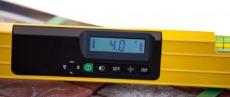
A one-time display of set and current temperature indicators is displayed using numbers and other symbols
Measuring high temperatures in furnaces. There can be no trifles
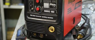
High temperatures (from 400–500 °C) in industry are most often measured by thermoelectric converters - thermocouples. But it happens that when installing and operating such sensors, the manufacturer’s recommendations are not followed. Thermocouples quickly fail and no longer meet the stated metrological characteristics. This article presents the results of modeling and experiment conducted on thermal converters manufactured by the OWEN company. Various options for installing the sensor on a furnace were compared at several values of measured temperatures, as a result of which recommendations were developed for long-term uninterrupted operation of thermocouples.
OWEN company, Moscow
General information about thermocouples
The thermocouple is one of the most common temperature sensors used in industry. In general, the sensor consists of two wires made of dissimilar metals, soldered at both ends. One junction – “hot” – is immersed in a medium with a measured temperature, the other – “cold” – is at a constant temperature (usually 0 ˚C). A thermoelectromotive force (TEMF) will arise in this closed loop, and it will depend only on the temperature difference between the junctions. By integrating a millivoltmeter into this circuit, it is possible to measure thermoEMF, which in this case will depend only on the change in the temperature of the “hot” junction, since the “cold” junction is in isothermal conditions. Let us immediately make a reservation that the above diagram is a general definition of a thermocouple, and only researchers measured its TEMF in such a laborious manner. Now everything is much simpler: the “cold” junction does not need to be maintained at a constant temperature; the correction is made by a secondary device - a meter or controller, which also acts as a millivoltmeter.
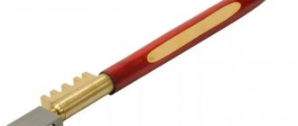
A thermocouple placed inside a protective fitting, equipped with a head for connecting an extension cable or a cable outlet, has the right to be called a thermoelectric converter (Fig. 1), but in everyday life, for the sake of brevity, such sensors are still called thermocouples.
Rice. 1
. Thermoelectric converter
Modern manufacturers offer a wide range of thermoelectric converters for almost any task. Various materials of covers - steels, alloys, ceramics, polymers - protect thermoelectrodes from aggressive and high-temperature environments. Various output signals – native (mV), analog (0(4)…20 mA, 0…10 V), digital (HART, RS‑485, Foundation Fieldbus, etc.) – allow these sensors to be integrated into any automation systems.
A huge selection of modifications of temperature sensors often forces you to seek additional advice from the technical specialists of the manufacturer: you need to take into account all the pitfalls of using the sensor, the specifics of its installation, select additional equipment, etc. An error in the selection of primary transducers can be costly. There are cases when, due to incorrect selection of the sensor, all heat-treated products are rejected. For example, thermocouples of the XA type (chromel-alumel) will not last long when installed on a furnace whose atmosphere contains 2–3% oxygen: selective oxidation of chromium in chromel will lead to a decrease in its thermoelectric power and corrosion of the thermoelectrode (“green rot”). When using thermocouples XA, XK (chromel-copel), NN (nichrosil-nisil) in a reducing atmosphere (where, in particular, carbon monoxide CO or hydrogen H2 are present), it is necessary to reliably protect the thermoelectrodes from the negative influence of the environment. For example, you can choose thermal converters based on KTMS (thermocouple cable with mineral insulation in a steel sheath).
Sensors with cable output based on KTMS are one of the simplest in design. But there are also subtleties in the selection and operation of such sensors that must be taken into account. About this in today's article.
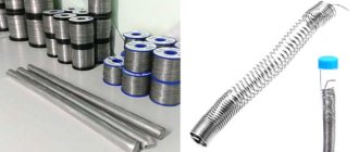
As an example, consider a thermocouple based on KTMS with a cable output OWEN DTPHxx4. Most often, such models of thermal converters (Fig. 2, 3) are installed on furnaces of various industries - from brick firing to metallurgy. They are used to measure the temperature of the charge, the furnace atmosphere, and exhaust gases in the smoke duct.
Rice. 2.
General view of a temperature sensor with a cable output based on KTMS OWEN DTPHxx4
Rice. 3
. Design ARIES DTPХхх4
The mounting (submersible) part L is a flexible MCT, inside of which a “hot” junction is located at the plugged end. MLC can have different diameters D: from 1.5 to 4.5 mm. The choice of diameter depends on the size of the mounting hole, the need for bending, and the level of measured temperatures. The cable terminal l of such a sensor is usually made of a thermocouple cable in a silicone sheath, which serves to connect the thermocouple to the secondary device and is usually located outside the measurement object at a relatively low temperature (up to 200 °C).
The nominal static characteristics (NSC) of such sensors according to GOST 8.585 are TXA (K), TXK (L), TZhK (J), TNN (N). The highest temperature can be measured by thermocouples with NSKh types K and N - 900...1250 °C. The last measurement temperature is valid only for type N. Also in the design of such a sensor there is a thin-walled metal tube with a diameter of 6 mm and a length of 50 mm - the so-called adapter sleeve (Fig. 3). Inside it there is a connection between the terminals of the KTMS thermoelectrodes and the thermoelectrodes of the thermocouple silicone cable.
When installing on a measurement object (for example, a furnace), it is allowed to immerse the thermocouple along the entire length of the mounting part L, but on the condition that when operating the sensor, the temperature at the adapter sleeve should not exceed 200 °C. If this condition is violated, the silicone insulation will begin to deform and melt, exposing the thermoelectrodes and destroying the “KTMS-cable outlet” connection. When selecting and installing the sensor, this condition must be taken into account. Sometimes a miscalculation in determining the temperature on the adapter sleeve leads to the failure of dozens of expensive sensors, furnace shutdowns and millions of losses. The difficulty is that the temperature of the adapter sleeve is influenced by several conditions: the maximum temperature in the furnace, the thickness of the furnace wall, the material of the furnace lining, the temperature of the air surrounding the furnace, the type of sensor installation (horizontal or vertical) and, most importantly, the distance from the outer surface of the furnace to the adapter bushings.
Heating simulation
OWEN engineers simulated the most severe operating temperature conditions for this sensor model: the temperature in the working space of the furnace is 1250 °C, a type N thermocouple with a mounting part diameter of 3 mm is immersed in the furnace, the shell material is KTMS - Nicrobell. Vertical installation, in the hole in the furnace roof.
The furnace roof material is fireclay-fiber slabs ShVP‑350. On the outside they are covered with a thin-walled metal casing. Ambient temperature 60 °C. The simulation was carried out using the Solid Works software and hardware complex, which allows for thermal calculations and the construction of solid body heating models.
In table Figure 1 shows two options for modeling the operating conditions of the sensor: - model No. 1 - the adapter sleeve is located close to the outer surface of the furnace (casing); — model No. 2 – the adapter sleeve is located at a distance S = 30 mm from the outer surface of the furnace (casing).
Table 1.
Two options for modeling sensor operating conditions
In Fig. Figure 4a shows the temperature gradient along the length of the sensor when completely immersed in the oven. Thus, under these operating conditions, the bushing will heat up to almost 300 °C, which is unacceptable.
In Fig. Figure 4b shows how the temperature of the sensor mounting part changes with distance from the hot working space of the furnace in the case of a larger lining thickness and the sleeve is removed only 30 mm from the wall; on the bushing itself the temperature is almost 100 °C, which is quite acceptable. Under such operating conditions, the thermal converter will last for years.
Rice. 4
. Options for modeling the operating conditions of the sensor: a – model No. 1. Temperature distribution along the length of the sensor, the sensor is completely immersed in the oven; b – model No. 2. Temperature distribution along the length of the sensor, the sleeve is moved away from the furnace wall to a distance S of indentation = 30 mm (
)
Experiment on a real furnace
OWEN engineers then conducted an experiment on a real furnace at the most common heat treatment temperatures: 700, 900 and 1000 °C. The object of measurement is the MTP-2 M-50-500 tube furnace. The marking of the thermocouple under test is DTPK444-09.200/3.0S.1, the diameter of the mounting part is 4.5 mm, length L is 200 mm. A general view of the stand for the experiment is shown in Fig. 5.
Rice. 5
. Experiment stand: general view
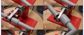
Experimental conditions: initially, the DTPK444 thermocouple was completely immersed up to the adapter sleeve in a preheated oven, installation was horizontal. The temperature of the adapter sleeve was measured using a small-sized thermocouple DTPL011, the junction of which was pressed to the sleeve and secured with a silica thread (Fig. 6a). Both sensors were connected to a two-channel ARIES TRM202 meter.
Rice. 6
. Stages of the experiment: a – thermocouple DTPK444 is completely (“all the way”) immersed in the furnace; b – the sleeve of the DTPK444 thermocouple is moved away from the furnace wall by 10 mm
Then, during the experiment, the depth of immersion of this sensor into the furnace was reduced by 10 mm, that is, the adapter sleeve was moved away from the furnace wall by this distance (Fig. 6b). Every 10 minutes the temperature in the furnace and the temperature of the sleeve were recorded. The results of the experiment are shown on the graph (Fig. 7).
Rice. 7
. Graph of temperature changes in the furnace and on the adapter sleeve
A total of 18 measurements were made: the first 8 were taken at a temperature in the furnace of 700 ± 10 °C, the sleeve was moved close to the furnace wall. The sleeve temperature has almost stabilized at 120 °C.
The next three measurements (Nos. 9, 10 and 11) the temperature in the furnace was 900 °C, while the temperature of the sleeve increased to 180 °C.
Then, from measurements No. 12 to No. 18, the furnace was heated to 1000 °C, but before measurement No. 15 the sleeve was also moved close. The graph clearly shows that the temperature of the adapter sleeve at such temperatures and installation reached 195 °C, almost a critical temperature, above which the silicone insulation will fail.
But if you slightly reduce the immersion depth of the sensor by moving the adapter sleeve only 10 mm from the wall, at the same temperature of the furnace working space of 1000 °C, the temperature at the sleeve will drop to an acceptable 150 °C. This can be seen on the graph (measurements nos. 16, 17 and 18).
Conclusions and recommendations
Modeling and experiment showing the heating nature of thermoelectric converters DTPHxx4 based on KTMS were carried out in order to establish the dependence of the temperature of the structural element, the adapter sleeve, the temperature of which during operation of the sensor should not exceed 200 °C, on the temperature in the furnace and the distance between the sleeve and the outer surface of the furnace . Heating the sleeve above 200 °C is unacceptable due to the destruction of the insulation (most often silicone) of the thermocouple wire, crimped inside the sleeve and used to connect thermocouples of this design to secondary devices.
Based on the results of both modeling and experiment, several important conclusions can be drawn for practical thermometry: - when measuring temperatures over 1000 °C with sensors permanently installed at the facility, it is not recommended to move their switching elements (adapter bushings, switching heads) close to the walls of the unit in order to avoid overheating and their failure; — when choosing a thermal converter, it is necessary to provide a “margin” along the length of the mounting part of the sensor; The “reserve” for the length of the mounting part can be quite small, in the general case – 10...20 mm. This offset distance S will be sufficient to avoid overheating of the switching element.
Published in the ISUP magazine No. 3(81)_2019
A.S. Sidortsev, product manager “Temperature sensors”, V.A. Zlobin, design engineer, OWEN company, Moscow, phone: +7 (495) 641‑1156, e‑mail, website: owen.ru
Functions performed by the muffle furnace control unit
The digital control unit of the muffle furnace with a microprocessor controller is not only simple, but also easy to use. With it you can:
- Perform high-precision heat treatment.
- Set the required temperature with minimal errors.
- Install a full operating cycle of heating equipment.
To make the muffle electric furnace 3 1100 or another model easy to use, it is enough to install a thermostat. You can select it taking into account the characteristics of the equipment used.
Modern control units for muffle furnaces are equipped with a convenient push-button keyboard and high-contrast LED indication
Programmable control of the muffle furnace allows you to set the holding, heating or cooling period. If a connection to a computer is provided, the operation of the unit can be monitored remotely.
Heating the muffle with gas
A homemade muffle furnace can operate not only from electricity, but also under the influence of a gas burner. You can purchase such a heating element or make it yourself.
To create a gas burner, you need a metal pipe 10-15 centimeters long. The diameter of the pipe should not exceed a few centimeters. First, you should make a through hole near the edge for connecting the gas tube. It is also necessary to make several one-sided holes perpendicular to it. They are necessary to ignite the device.
For a gas burner you will need a metal pipe 10-15 centimeters long
The gas tube is made of copper, its diameter does not exceed 0.8 centimeters. Threads are required at both ends of the tube. In the middle of the device you need to make a small blind hole for the gas to escape. One hole must be closed with a plug, and a gas cylinder must be connected to the other. When combining elements of the device, be sure to install a valve between the hose and the burner, as it will protect the structure from fire.
How to assemble a control unit for a muffle furnace with your own hands
When making a muffle furnace with your own hands, you can not bother and buy a ready-made electric furnace control unit, using what is written above to select a model. But many craftsmen, confident in their abilities, prefer to assemble this device themselves. And this is what the second part of our article is about. We will tell you how and from what parts you can assemble the “brain” of your stove yourself.
The use of electronic programmers allows you to maintain the operation of the electric furnace in automatic mode, with minimal human intervention
- Elena:
09.24.2017 at 07:10
Thanks a lot. The article is very helpful. Right now we are building our own kiln. True, we use ARIES 251, but the essence is clear. Your articles are very useful, we consider your site as a reference book for dummies. Thank you again for not being greedy and sharing the necessary information.
Answer
- Yuri Gorniy:
09.24.2017 at 12:45
Please) Only when connecting Aries is it easier to use a solid-state relay instead of a triac.
Answer
Elena:
09/30/2017 at 08:17
Yes, we also purchased a solid state relay.
Answer
- Yuri:
07/26/2019 at 11:35
Thank you, kind man!
Answer
- Ivan:
01/12/2021 at 12:18
Need advice on control unit
Answer
What elements does the muffle furnace control unit consist of?
Let us list what devices you need to use to independently assemble the muffle furnace control unit. The electrical part includes the following components:
Thermostat
As already mentioned, the thermostat for a muffle furnace is selected depending on the area of activity. There are two main types:
- Mechanical . This type of device is familiar to everyone - a dial with divisions and a handle. The desired temperature is set by turning it to the desired mark. This device is quite primitive and does not allow achieving accurate indicators.
- Digital . The simplest is an electronic device with a screen that displays the set and current temperature. It can be additionally equipped with a timer. Devices that allow you to control the heating rate and operating time have become widespread. After completion of the operation, the regulator automatically turns off. Models with a built-in programmer are used to perform multi-stage tasks.
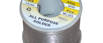
Thermocouple
A muffle furnace thermocouple is designed to measure the temperature inside the chamber. Data from it is sent to the thermostat, which controls the work process. This sensor is located on the back wall of the camera in a pre-prepared hole. For electric furnaces, thermocouples with the names “HK”, “XA” and “PP” are used. They are connected through special connectors or using electrical terminals secured to the housing with screws and nuts.
Copper wires can be used to connect the thermocouple to the terminal, since there is no temperature difference
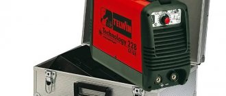
Relay and radiator
The kit consists of a cooling radiator and a communicator attached to it. Most often, a solid-state semiconductor relay is installed, which can withstand fairly high heat.
Switch
Used to start the muffle furnace into operation. There is no fundamental difference whether to use a device with two keys or mount two single-key switches next to each other.
All of these devices are combined into a common circuit. To make work easier, you can purchase a ready-made unit with a relay and heat regulator. In this case, all that remains is to connect the temperature sensor for the muffle furnace and the heating coil to it
Thermal insulation of the furnace
As a result of the described actions, an almost ready-made firebox of the hardening furnace is obtained; it only needs to be placed in the housing, securely fastened and heat loss minimized. For this purpose, a pre-made container with legs is useful.
The internal volume of the container must be filled with mineral wool with a density of 45–50 kg/m3. The cotton wool needs to be rolled into a spiral, first placing it under the outer walls and gradually moving towards the center. The packing density should be maximum, but the wool itself should not be damaged. As a result, the firebox assembly needs to be placed in the central fold. If the density of the wool is sufficient, the heating part will not crush the insulation with its weight. All leads of the spirals must be carefully wrapped with fiberglass, spacers made from scraps of mineral wool must be inserted between them, and then brought out through the back wall, connected to the back side of the studs and the panel installed in place.
To securely secure the firebox and install the door, the cotton wool needs to be pressed down and sunk 6–8 cm deeper than the sides. The surface of the insulation needs to be sprinkled with alabaster milk several times so that the cotton wool hardens and stops intensively absorbing moisture. After this, the front part of the furnace is filled with a mixture of alabaster, sand and mineral fiber. While the composition has not hardened, a fire door or mortgages are built into it to secure it.