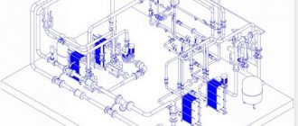
Pipelines - underground and aboveground - are one of the most important communications of cities, farms, and enterprises. Water supply and water treatment systems, transportation of liquid media, heating, gas and oil pipelines - all these are pipeline assemblies. The smoothness of their operation, safety and cost of maintenance depend on how well they are implemented.
There is a set of rules and technologies for the construction of pipelines for various purposes, compliance with which is regulated at the highest level. The standards for specific projects directly depend on the assembly method, and there are several of them.
Types of installation
All methods can be divided into 2 large groups.
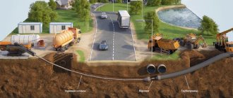
- Underground installation. It is used more often and is carried out using 1 of 2 technologies.
- Channelless pipeline installation.
- Underground device in channels.
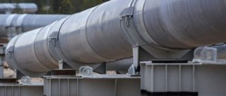
- Aboveground pipeline laying. It involves installing pipes on the ground surface or at a distance from it (relevant for pipelines above routes, in this case the height of the pipes must be sufficient so that the pipeline does not interfere with the operation of the route). Overhead pipelines are indispensable when the pipe route runs through ravines, transport routes, rivers, and other structures. Aboveground pipeline installation is carried out in channels (trays). They can be located on the ground or be slightly buried in it; this method of installation is relevant in regions with a cold climate, which is characterized by the presence of permafrost soils.
The choice of method for constructing a pipeline line depends on a number of conditions. Among them are planning factors (purpose, intersections of the route with structures and objects), natural (soil category), financial (construction budget) and others (requirements for the aesthetics of the type of engineering system). The decision on technology is made after calculations for various installation options and should be focused primarily on optimizing the cost of communication.
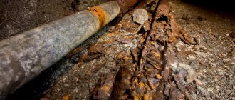
Moreover, the feasibility study should take into account not only the construction price, but also the service component of the project cost. Example - laying a heating pipeline . Choosing an underground device will reduce capital costs for construction. But in maintenance practice, the cost will be higher than that of above-ground installation due to:
- the need for insulation (with ductless installation, heat loss will be higher, especially in wet soil);
- additional ongoing support to prevent early wear.
Suspended pipeline supports
Pipeline hangers are steel products designed for fixing vertically and horizontally located pipelines to the enclosing structures of buildings.
Their functions are to compensate for vertical and horizontal movements of the pipeline and transfer its mass to the supporting structure. The main area of application of such hangers is the construction of pipeline systems of nuclear and thermal power plants. Suspended supports are produced in a wide range of designs from different materials.
Our catalog contains a wide range of pipeline hangers
Methods for constructing underground systems
The most common pipe laying methods are:
- trenchless (laying underground without opening the soil);
- open version (assembly on supports, can be carried out in through or non-through collectors);
- hidden installation method (trenches are prepared along which the pipes run).
The project can be complex or simple. In the first case (usually used for laying water supply pipelines in urban areas using the trench or channel method), several different mains can run in one trench - boxes with cables, a heating network and water supply, for example.
One of the important conditions for the longevity of the entire assembly is the choice of appropriate pipe material. In modern practice, products made of plastic, asbestos, metal (steel, copper), ceramics, and concrete are used.
Open way
The open method of laying a pipeline cannot be called a popular solution. Rather, it is a compromise that is relevant in cases where installation using a closed method is impossible.
Stages of work:
- preparing and leveling the trench for laying the pipeline ;
- strengthening the walls and bottom of the mine;
- sand cushion mound;
- installation (assembly) of pipes;
- covering pipe sections;
- closing the trench;
- leveling the surface and restoring the coating (if any) of the landscape object.
An open network can also be established in non-passable channels. Then the main pipes will not be subject to constant mechanical stress (pressure) during periods of soil movement and heaving. True, repairs are difficult due to less comfortable access directly to the sections.
The advantages of open underground pipeline installation include the possibility of its implementation in cases that exclude the hidden installation method. Minuses:
- high cost of the project (the need to carry out labor-intensive excavation work and restore the landscape);
- mandatory break in the operation of facilities along the route;
- creation of emergency zones at the site of soil opening.
Installation in ducts
Channels (trays) are used to protect pipes when they are located underground. Among the tasks that channel assemblies perform:
- insulation (primarily thermal);
- ensuring free extension of the pipe under the influence of high temperatures.
Channels are laid on movable supports under floors, including in highway areas. The minimum depth of placement of the tray is 0.6 m (vehicle traffic is prohibited) or 0.8–1.2 m (under an active road). The depth calculation is carried out taking into account the observance of 2 conditions: determining the minimum possible safe depth and ensuring the effective distribution of external loads (including vehicular loads) on the pipeline network.
Based on their design, they distinguish between through, non-through and semi-through pipeline (heat-conducting) channels. Regardless of the design, all trays are laid on supports. During installation, 2 types of slope are provided:
- longitudinal of the entire network by at least 0.002 to remove water (from the lowest points it is discharged into the drainage system by gravity, another option is to install pits and forcefully remove it into the sewer with a pump);
- transverse slope of the floors by 1–2% to remove atmospheric moisture and flood waters.
Additional protection against the destructive effects of moisture is used in areas with high groundwater levels. Here you need waterproofing of walls, ceilings, and channel bottoms.
Suspended pipeline supports
Design options
The MTS Center ZMK catalog contains pipeline hangers manufactured in strict accordance with the requirements of the regulations. The choice of a specific model depends on the type of pipeline, its design features and the grade of steel from which it is made.
- Suspended supports, manufactured in accordance with GOST 16127-78, are used for organizing pipeline systems that are intended to transmit media with temperatures of 0...+450°C and pressures of up to 10 MPa. Pipe diameter - 25-500 mm.
- Pendants manufactured in accordance with OST 24.125.ХХХ-01 are intended for use in pipeline networks of nuclear power plants and thermal power plants. Such hanging supports are suitable for seamless pipes made of carbon, chrome-molybdenum-vanadium, silicon-manganese steels, and electric-welded pipes made of carbon grades.
- Suspended supports in accordance with OST 34-10-723-93 are intended for pipelines of nuclear and thermal power plants. Operating temperature range -30...+425°C.
- Series 4.903-10, issue 6. Rigid supports for horizontal pipelines with diameters of 25-600 mm and spring supports for horizontal and vertical pipelines with diameters of 150-1400 mm. Spring models are in demand for pipeline systems in which there are displacements in various directions. The number of spring support blocks is determined by the dimensional parameters of the pipeline, the number and direction of loads. For systems in which exclusively axial loads act and only longitudinal displacements are possible, rigid suspensions are used. Most often, such hangers are used for horizontal pipelines. Diameter range - 25-600 mm.
- Pipeline hangers according to series 5.900-7, issue 4. Metal products of this group are used for fixing insulated and non-insulated pipes of plumbing systems for fixation to the surfaces of enclosing structures - walls, floors, ceilings.
- Series 5.900-13, issue 6-95 regulates rigid and spring suspensions used in heating networks.
Safe, reliable and durable operation of any modern pipeline is impossible if high-quality specialized structures are not used during the installation process.
It should be noted that such pipeline hangers are intended to withstand various serious loads (deformation, thermal expansion) affecting pipelines during their operation.
ZMK "MTS Center" sells rigid and spring suspensions of various types, produced in full compliance with regulatory documentation.
- the minimum possible time for the formation of the ordered batch;
- delivery of goods by transport from our own fleet, corresponding to the size of pipeline fittings and the volume of the ordered batch;
- technical consultations.
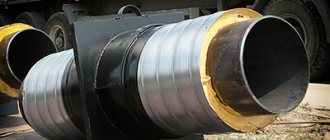
Channelless pipeline laying
Unlike the channel method, when installing systems without channels, movable supports and trays are not used. Channelless pipeline installation is widely used in regions with dry soils, although channelless systems are also installed (with drainage) on wet soils. The insulating shell acts as protection here. Features of channelless installation:
- preparing the trench for laying (its bottom should be as flat as possible);
- constructing a “pillow” of compacted sand, which should be at least 10 cm thick (for clay soils - 10–15 cm);
- the fixed supports for channelless installation are walls made of reinforced concrete (mounted at right angles to the pipeline);
- compensators are installed in niches (chambers), which can be gland or bent. They are responsible for compensating for pipe movements under the influence of temperatures during ductless installation.
The advantages of channelless installation include the favorable cost of pipeline construction, minimal amount of work, and short project implementation time. There are also disadvantages: difficult repairs and mechanical fixation (clamping) of pipes with soil, which complicates their thermal movement.
Rules for the design and safe operation of process pipelines (page 6)
5.4.5. When choosing materials for supporting structures, supports and suspensions placed outdoors and in unheated rooms, the average temperature of the coldest five-day period with a probability of 0.92 is taken as the design temperature.
The material of support and hanger elements welded to the pipeline must match the material of the pipeline.
For support and suspension elements in direct contact with the pipeline, the temperature of the transported substance should also be taken into account.
5.4.6. To ensure the design slope of the pipeline, it is permitted to install metal pads under the support pads, welded to the building structures.
5.4.7. For pipelines subject to vibration, supports with clamps should be used and placed on building structures. Hangers for such pipelines may be provided as an additional method of fastening.
5.4.8. The project, if necessary, indicates the values of preliminary displacement of the movable supports and suspension rods, as well as data on adjusting the spring supports of the suspensions.
When using suspensions in a project, rod lengths are indicated in the range from 150 to 2000 mm, multiples of 50 mm.
5.4.9. Pipeline supports must be installed in compliance with the following requirements:
a) they must fit tightly to building structures;
b) their deviation from the design position should not exceed ±5 mm in plan for indoor pipelines and ±10 mm for external pipelines; slope deviation should not exceed +0.001;
c) the slope of the pipeline is checked with instruments or special devices (level, hydrostatic level, etc.);
d) movable supports and their parts (the upper parts of the supports, rollers, balls) must be installed taking into account the thermal elongation of each section of the pipeline, for which the supports and their parts must be shifted along the axis of the supporting surface in the direction opposite to the elongation;
e) the suspension rods of pipelines that do not have thermal extensions must be installed vertically; the suspension rods of pipelines with thermal extensions must be installed with an inclination in the direction opposite to the extension;
f) the springs of the supports and suspensions must be tightened in accordance with the instructions in the design; during installation and hydraulic testing of pipelines, the springs are unloaded by spacer devices;
g) supports installed at the bottom of trays and channels must not interfere with the free flow of water along the bottom of the tray or channel.
5.4.10. If it is necessary to reduce friction forces, special bearing designs should be installed, including ball and roller bearings.
Roller and ball bearings are not allowed to be used when laying pipelines in channels.
5.4.11. Movable and fixed supports for pipelines containing hydrogen sulfide-containing media should, as a rule, be used with clamps. The use of support parts welded to the pipeline without subsequent heat treatment of the pipeline is not allowed.
5.4.12. Welding of moving support elements to pipelines made of thermally strengthened pipes and controlled rolling pipes is not allowed.
5.5. Additional requirements for the installation of pipelines for the complete block installation method
5.5.1. The design, manufacture and testing of pipelines included in the delivery units must comply with the requirements of these Rules and technical documentation for the design, manufacture and testing of pipeline units.
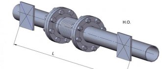
5.6. Compensation for temperature deformations of pipelines
5.6.1. Temperature deformations should be compensated by turns and bends of the pipeline route. If it is impossible to limit yourself to self-compensation (for example, on completely straight sections of considerable length), U-shaped, lens, wavy and other compensators are installed on pipelines.
In cases where the design provides for steam or hot water purging, the compensating capacity of the pipelines must be designed for these conditions.
5.6.2. It is not allowed to use stuffing box compensators on process pipelines transporting media of groups A and B.
Installation of lens, stuffing box and corrugated expansion joints on pipelines with a nominal pressure exceeding 10 MPa (100 kgf/cm) is not allowed.
5.6.3. U-shaped expansion joints should be used for process pipelines of all categories. They are made either bent from solid pipes, or using bent, steeply curved or welded elbows.
5.6.4. For U-shaped expansion joints, bent bends should be used only from seamless pipes, and welded bends should be used from seamless and welded straight-seam pipes. The use of welded bends for the manufacture of U-shaped expansion joints is permitted in accordance with the instructions of clause 2.2.37 of these Rules.
5.6.5. It is not allowed to use water and gas pipes for the manufacture of U-shaped expansion joints, and electric welded pipes with a spiral seam are recommended only for straight sections of expansion joints.
5.6.6. U-shaped expansion joints must be installed horizontally, maintaining the required overall slope. As an exception (if the area is limited), they can be placed vertically with a loop up or down with an appropriate drainage device at the lowest point and air vents.
5.6.7. Before installation, U-shaped compensators must be installed on pipelines together with spacer devices, which are removed after securing the pipelines to fixed supports.
5.6.8. Lens expansion joints, axial, as well as hinged lens expansion joints, are used for process pipelines in accordance with the regulatory and technical documentation.
5.6.9. When installing lens compensators on horizontal gas pipelines with condensing gases, condensate drainage must be provided for each lens. The drainage pipe connection is made of seamless pipe. When installing lens compensators with an internal cup on horizontal pipelines, guide supports must be provided on each side of the compensator at a distance of no more than 1.5 D
compensator.
5.6.10. When installing pipelines, compensating devices must be pre-stretched or compressed. The amount of preliminary stretching (compression) of the compensating device is indicated in the design documentation and in the pipeline passport. The amount of stretch can be changed by the amount of correction taking into account the temperature during installation.
5.6.11. The quality of expansion joints to be installed on process pipelines must be confirmed by passports or certificates.
5.6.12. When installing a compensator, the following data is entered into the pipeline passport:
technical characteristics, manufacturer and year of manufacture of the compensator;
the distance between the fixed supports, the necessary compensation, the amount of pre-tension;
ambient air temperature when installing the compensator and date.
5.6.13. Calculation of U-shaped, L-shaped and Z-shaped compensators should be made in accordance with the requirements of regulatory and technical documentation.
5.7. Requirements for reducing pipeline vibration
5.7.1. For equipment and pipelines that are subject to vibration during operation, designs should include measures and means to reduce vibration and eliminate the possibility of emergency destruction and depressurization of the system.
Methods for reducing and permissible levels of vibration, methods and means of controlling it must comply with the requirements of state standards and other regulatory documents.
5.7.2. To eliminate vibration of pipelines from flow pulsation in piston machines, provision must be made for the installation of buffer and acoustic tanks, justified by appropriate calculations, and, if necessary, the installation of special pulsation dampers.
When several compressors operate on a common manifold, buffer and acoustic tanks must be installed for each injection unit.
5.7.3. The design and dimensions of buffer and acoustic tanks for pulsation damping and installation locations are selected based on the calculation results.
Devices included with the compressor (refrigerators, separators, oil separators, etc.) can be used as a buffer tank to dampen pulsation, subject to appropriate verification by calculating the volume and installation location of the device.
5.8. Thermal insulation, heating
5.8.1. The need to use thermal insulation is determined in each specific case, depending on the properties of the transported substances, the place and method of laying the pipeline, the requirements of the technological process and the requirements of occupational safety and explosion and fire safety.
5.8.2. Pipelines are subject to thermal insulation in the following cases:
if it is necessary to prevent and reduce heat or cold loss (to maintain temperature, prevent condensation, the formation of ice, hydrate or other plugs, etc.);
when the temperature of the pipeline wall outside the working or service area is above 60 °C, and at the workplace and in the service area at a temperature above 45 °C - to avoid burns;
if necessary, ensure normal temperature conditions in the room.
In justified cases, the thermal insulation of pipelines can be replaced by enclosing structures.
5.8.3. Thermal insulation of pipelines must comply with the requirements of regulatory and technical documentation.
5.8.4. When laying a pipeline with heated satellites, thermal insulation is carried out together with the heated satellites.
The need for heating, the choice of coolant, the diameter of the heated satellite and the thickness of thermal insulation are determined by the project based on appropriate calculations.
5.8.5. Thermal insulation of pipelines is carried out after testing them for strength and density and eliminating all defects detected.
Heating satellites must also be tested and accepted by the act committee before thermal insulation is applied.
When installing heating satellites, special attention should be paid to the absence of hydraulic “bags” and correct drainage at all low points.
5.8.6. The following elements should be provided in the thermal insulation structures of the pipeline:
main heat-insulating layer;
reinforcing and fastening parts;
protective covering layer (protective coating).
Thermal insulation structures of pipelines with temperatures of transported substances below 12 °C must include a vapor barrier layer. The need for a vapor barrier layer at temperatures of transported substances above 12 °C is determined by calculation.
At negative operating ambient temperatures, the thermal insulation design must provide for careful sealing of all joints of individual elements and sealing of seams when installing prefabricated thermal insulation structures.
5.8.7. For fittings, flange connections, compensators, as well as in places for measuring and checking the condition of pipelines, removable heat-insulating structures must be provided. The thickness of the thermal insulation of these elements should be taken equal to 0.8 of the thickness of the thermal insulation of the pipes.
5.8.8. For pipelines with operating temperatures above 250 °C and below -60 °C, the use of single-layer heat-insulating structures made of molded products (perlite-cement, lime-silica, sovelite, vulcanite) is not allowed.
5.8.9. It is not allowed to use elements of thermal insulation structures made of combustible materials for pipelines of groups A and B, as well as pipelines of group B for overhead installation, for intra-shop ones, located in tunnels and on evacuation routes for operating personnel (corridors, staircases, etc.).
5.8.10. For pipelines transporting active oxidizers, it is not allowed to use thermal insulation containing organic and flammable substances of more than 0.45% by weight.
5.8.11. Thermal insulation materials and products containing organic components are allowed for use on pipelines with an operating temperature above 100 °C if there are appropriate justifications.
5.8.12. For pipelines subject to vibration, it is not recommended to use powdered thermal insulation materials, mineral wool and continuous glass wool.
5.9. Corrosion protection and painting of pipelines
5.9.1. When transporting aggressive substances, protection against corrosion of the internal surface of steel pipelines should be ensured taking into account the chemical and physical properties of the substances, the design and materials of pipeline elements, operating conditions and other factors.
5.9.2. The choice of the type and system of protection against corrosion of the outer surface of pipelines is carried out depending on the method and conditions of their installation, the nature and degree of corrosive activity of the external environment, the degree of danger of electrocorrosion, the type and parameters of the transported substances.
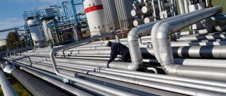
5.9.3. Assessment of the degree of aggressiveness of environmental influences and protection against corrosion of the outer surface of above-ground pipelines should be carried out using metallic and non-metallic protective coatings in accordance with the requirements of building codes and regulations.
5.9.4. To protect pipelines from underground corrosion, the project provides solutions to ensure their reliable operation.
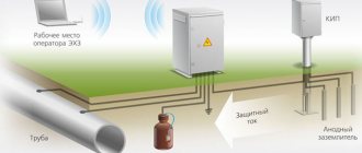
5.9.5. The decision on the need for electrochemical protection is made in accordance with the requirements of the normative and technical documentation on the basis of corrosion studies carried out in order to identify the danger of soil corrosion or corrosion by stray currents in pipeline laying areas.
5.9.6. The design of an electrochemical protection system (cathodic, sacrificial, drainage) must be carried out in accordance with the requirements of regulatory and technical documentation.
5.9.7. When laying underground pipelines without channels, the design of means of protection against soil corrosion and corrosion caused by stray currents should be carried out for pipelines without thermal insulation.
5.9.8. Pipelines transporting substances with temperatures below 20 °C and subject to thermal insulation should be protected from corrosion, like pipelines without thermal insulation.
5.9.9. When electrochemical protection of pipelines, insulating flange connections (IFS) should be provided. Placement of IFS is in accordance with building codes and regulations.
5.9.10. To measure electrical potentials, it is allowed to use disconnecting devices, condensate collectors and other equipment and structures.
5.9.11. When designing measures for anti-corrosion protection of process pipelines, design solutions must ensure accessibility of inspection and restoration of anti-corrosion coatings.
5.9.12. Identification painting and marking of pipelines and their elements should be carried out in accordance with state standards and regulatory and technical documentation on industrial safety.
VI. Requirements for installation of pipelines
6.1. General requirements for pipeline installation
6.1.1. Installation of pipelines and communication units (hereinafter referred to as pipelines) should be carried out in accordance with the requirements of these Rules, the developed work plan (WPP) and the project.
Installation of pipelines of explosion- and fire-hazardous industries with blocks of explosion hazard category I should, as a rule, be carried out on the basis of a node or assembly-block method.
6.1.2. Deviation from the project and the PPR is not allowed without approval in the prescribed manner.
6.1.3. When installing pipelines, incoming quality control of materials, pipeline parts and fittings should be carried out for compliance with their certificates, standards, technical specifications and other technical documentation, as well as operational quality control of the work performed. The results of the incoming inspection are documented in a report attaching all documents confirming the quality of the products.
6.1.4. The deviation of the linear dimensions of pipeline assembly units should not exceed ±3 mm per 1 m, but not more than ±10 mm over the entire length.
6.1.5. Products and materials for which the estimated periods specified in the documentation have expired can be transferred for installation only after an audit, elimination of defects, testing, examination and other work ensuring their quality and safety of use.
6.1.6. Storage conditions for products and materials for pipeline installation must comply with the requirements of technical documentation.
6.1.7. If a pipe is cut into several parts during installation, then all newly formed parts are marked with a mark corresponding to the mark of the original pipe.
6.2. Pipeline installation
6.2.1. When accepting assembly units, pipes, elements and other products included in the pipeline for installation, it is necessary to check their compliance with the documentation requirements and completeness by visual inspection (without disassembly).
6.2.2. Installation of assembly units, pipes, parts and other products that are dirty, damaged by corrosion, deformed, or with damaged protective coatings is not allowed.
6.2.3. Special types of cleaning of internal surfaces of pipelines (degreasing, etching), unless otherwise indicated in the documentation, can be performed after installation during the commissioning period.
6.2.4. Pipelines may only be connected to equipment fixed in the designed position. Pipelines should be connected to equipment without distortion or additional tension. Fixed supports are attached to the supporting structures after the pipelines are connected to the equipment.
6.2.5. When assembling pipelines for welding, no load is allowed on the welded joint until it has completely cooled after welding and heat treatment (if necessary).
6.2.6. The distance from the transverse welded joint to the edge of the support or suspension should provide (if necessary) the possibility of its heat treatment and control.
The distance from the fitting or other element with a fillet (T) weld to the beginning of the bent section or transverse weld of the pipeline must be no less than the outer diameter of the pipe, but not less than 50 mm for pipes with an outer diameter of up to 100 mm. For pipes with an outer diameter of 100 mm or more, this distance must be at least 100 mm.
The length of the straight section between the welds of two adjacent bends must be at least 100 mm for a nominal diameter of less than 150 mm and 200 mm for a nominal diameter of 150 mm and above. When using steeply curved bends, it is allowed to place welded joints at the beginning of the curved section and weld bends without straight sections to each other.
6.2.7. The distance between adjacent welded joints and the length of the ring inserts when welding them into the pipeline must be at least 100 mm.
6.2.8. Welding of fittings, bosses, couplings and other parts at the locations of welds, into bent and stamped parts of pipelines is not allowed.
In justified cases, welding of one fitting with an internal diameter of no more than 25 mm is allowed into bent and stamped pipeline parts.
6.2.9. When assembling transverse welded joints, the longitudinal welds of the elements being connected must be shifted by rotating around the longitudinal axis of the elements relative to each other.
6.2.10. Before installing the pipeline assembly units in the design position, the nuts on the bolts (studs) of the flange connections must be tightened, the welded joints must be welded (if necessary, heat treated) and checked in accordance with the documentation requirements.
6.2.11. The deviation from the perpendicularity of the sealing surface of the flange to the axis of the pipe or part should not exceed the values given in table. 8.
Table 8
Deviation from perpendicularity to the axis of the sealing surface of the flange
| #G0Pipe diameter (parts), mm | Deviation, mm |
| 25-60 | 0,15 |
| 60-160 | 0,25 |
| 160-400 | 0,35 |
| 400-750 | 0,5 |
| Over 750 | 0,6 |
6.2.12. The misalignment of the sealing surfaces of the mating flanges should not exceed twice the deviation indicated in the table. 8, in this case the gap should be the same around the entire circumference and correspond to the thickness of the gasket.
6.2.13. When assembling flange connections, the following requirements must be met:
the bolt nuts must be located on one side of the flange connection;
the height of the ends of bolts and studs protruding above the nuts must be at least 1 and no more than 3 thread pitches;
nuts of connections with soft gaskets are tightened in a crosswise manner, and with metal spacers - in a circular manner;
bolts and studs of pipeline connections must be lubricated in accordance with the requirements of the working documentation, and pipelines operating at temperatures above 300 °C must be pre-coated with graphite lubricant. Soft gaskets are rubbed on both sides with dry graphite;
the diameter of the gasket hole must not be less than the internal diameter of the pipe and must correspond to the internal diameter of the sealing surface of the flange;
It is not allowed to level out distortions of flange connections by tensioning bolts (studs), or by using wedge gaskets.
6.2.14. Installation of the pipeline is permitted only after installation and fastening of supporting structures and hangers in accordance with the requirements of the project. Assembly units and pipeline assemblies must be laid on at least two supports (or secured on two hangers) and protected from tipping over or turning around.
6.2.15. The distance from the valve flange or compensator flange to the support, suspension, wall, partition, or ceiling must be at least 400 mm.
6.2.16. At the locations of the measuring diaphragms, instead of them during installation, it is allowed to temporarily install mounting rings in accordance with the regulatory and technical documentation.
6.2.17. Valves that have a mechanical or electric drive must undergo a performance check of the drive before being handed over for installation.
6.2.18. The position of the valve body relative to the direction of medium flow and the installation of the steering wheel axes are determined by the project.
6.2.19. Pipe fittings should be installed in a closed state. Flange and welded connections of fittings must be made without tension in the pipeline. When welding welded fittings, its shutter or valve must be fully opened to prevent it from jamming when the body heats up. If welding is carried out without backing rings, the fittings can be closed at the end of welding only after internal cleaning.
6.2.20. Cold tensioning of pipelines can be carried out after all welded connections have been completed (except for the closing one), final fastening of fixed supports at the ends of the section subject to cold tension, as well as after heat treatment (if necessary) and quality control of welded joints located along the entire length of the section , on which it is necessary to perform a cold tension.
6.2.21. U-shaped expansion joints located in a horizontal plane should be installed in compliance with the general slope of the pipeline specified in the working documentation.
6.2.22. Axial expansion joints should be installed coaxially with the pipelines.
Permissible deviations from the design position of the connecting pipes of expansion joints during their installation and welding must comply with the documentation for expansion joints.
6.2.23. When installing compensators, the direction of the arrow on their body must coincide with the direction of movement of the substance in the pipeline.
6.2.24. When installing compensators, torsional loads relative to the longitudinal axis and their sagging under the influence of their own weight and the weight of adjacent pipelines must be excluded, and the flexible element must also be protected from mechanical damage and sparks during welding.
6.2.25. The installation length of bellows, lens and stuffing box expansion joints is taken taking into account corrections for the outside air temperature during installation.
6.2.26. Expansion joints should be stretched to the installation length using devices provided by the compensator design, or tension mounting devices. The stretching (compression) of compensators is documented in a document.
6.2.27. When installing stuffing box expansion joints, the free movement of moving parts and the safety of the packing are ensured.
6.2.28. The welded joint, before welding of which the expansion joint must be stretched, must be indicated in the working documentation. It is allowed to use a connection located at a distance of at least 20 D
from the axis of symmetry of the compensator.
6.2.29. Lens, bellows and stuffing box expansion joints should be installed in assembly units and communication blocks during their enlarged assembly, using additional rigidity to protect the expansion joints from deformation and damage during transportation, lifting and installation. Upon completion of installation, the temporarily installed rigidities are removed.
6.2.30. The deviation of pipelines from the vertical (if there are no instructions in the project) should not exceed 2 mm per meter of pipeline length.
6.2.31. When installing vertical sections of pipelines, the working documentation must provide for measures to exclude the possibility of compression of expansion joints under the influence of the weight of the vertical section of the pipeline.
6.2.32. The final fastening of pipelines in each temperature block when laying on overpasses, in channels or trays must be done starting from the fixed supports.
6.2.33. Installation of pipelines crossing railways, roads, driveways and other engineering structures should be carried out by agreement in the prescribed manner.
6.2.34. For heating process pipelines, pipelines D
not less than 20 mm with their connection by welding (except for places where flange fittings are installed).
6.2.35. The fastening of heating pipelines to process pipelines must ensure free compensation of thermal elongations of the pipelines.
6.2.36. Anti-corrosion protection and thermal insulation of pipelines before installing them in the design position may be carried out under the condition of ensuring the safety of the protective coating during subsequent installation work.
6.3. Features of installation of pipelines with nominal pressure over 10 MPa (100 kgf/cm) to 320 MPa (3200 kgf/cm)
6.3.1. Assembly units and pipeline parts must comply with state standards and regulatory and technical documentation. When accepting pipelines and other products for installation, you should check:
threaded connecting ends of pipes, parts and fittings - by turning the flanges;
thread the studs - by turning the nuts;
geometric dimensions of the connecting ends of pipes and connecting parts, fittings, flanges, couplings, fasteners and gaskets in the amount of 2% of each batch, but not less than 2 pieces;
compliance of the number of pipes, connecting parts, flanges, lenses, couplings, fittings, fasteners and gaskets with the quantity specified for these lots in the accompanying documentation.
Pipeline fittings, regardless of testing and warranty period, are subject to strength and tightness testing before being issued for installation.
6.3.2. Requirements for cleaning, lubrication, assembly, alignment and clearances in detachable connections of pipelines are established in the design documentation or normative and technical documentation.
It is not allowed to eliminate gaps, non-parallelism or misalignment between assembly units or parts by tensioning pipelines.
6.3.3. Fasteners must be from the same batch and tightened using tension control devices. The procedure for assembling connections and monitoring tightening forces must be given in the regulatory and technical documentation or production instructions (routine sheet), taking into account the values given in the working documentation or (if not available) in the table. 9.
Table 9
The magnitude of the tightening force of the studs
| #G0Dia- | Tightening force*1 of one stud (kN) at nominal pressure, MPa (kgf/cm) | ||||||||||
| meter conditional much about stroke, mm | 20 (200) | 25 (250) | 32 (320) | 40 (400) | 50 (500) | 64 (640) | 80 (800) | ||||
| 6 | 1,1 | 1,2 | 1,3 | 1,5 | 1,5 | 1,9 | 2,2 | 2,5 | 24,0 | 24,0 | 30,0 |
| 10 | 3,1 | 3,3 | 3,7 | 4,0 | 4,5 | 5,2 | 6,0 | 6,6 | 36,0 | 36,0 | 40,6 |
| 15 | 7,0 | 7,5 | 8,2 | 6,8*2 | 7,6*2 | 8,8 | 10,0 | 11,5 | 48,0 | 48,0 | 55,0 |
| 9,0 | 10,0 | ||||||||||
| 25 | 11,8 | 12,7 | 13,9 | 15,8 | 17,0 | 19,7 | 22,6 | 26,0 | 46,5 | 46,5 | 74,1 |
| 32 | 21,0 | 22,5 | 24,5 | 27,0 | 20,0*2 | 23,0 | 26,5 | 31,0 | 64,5 | 64,5 | 100,3 |
| 30,0 | |||||||||||
| 40 | 21,0 | 22,5 | 24,5 | 27,0 | 30,0 | 34,5 | 39,5 | 46,0 | 75,5 | 82,0 | 135,5 |
| 50 | 37,5 | 40,0 | 44,0 | 48,5 | 54,0 | 62,5 | 71,0 | 82,5 | 91,0 | 99,8 | 150,0 |
| 65 | 51,5 | 55,0 | 60,0 | 67,0 | 74,0 | 85,0 | 98,0 | 114,0 | 124,0 | 134,5 | 167,8 |
| 80 | 77,0 | 82,0 | 90,0 | 99,0 | 110,0 | 95,0*2 | 110,0*2 | 127,0 | 155,2 | — | — |
| 127,0 | 145,0 | ||||||||||
| 100 | 100,0 | 107,0 | 117,0 | 97,0*2 | 108,0*2 | 124,0 | 142,0 | 165,0 | — | — | — |
| 130,0 | 144,0 | ||||||||||
| 125 | 116,0 | 125,0 | 136,0 | 151,0 | 168,0 | 194,0 | 222,0 | 257,0 | — | — | — |
| 150 | 173,0 | 185,0 | 200,0 | 223,0 | 250,0 | 286,0 | 327,0 | 380,0 | — | — | — |
| 200 | 280,0 | 300,0 | 330,0 | 290,0*2 | 324,0*2 | 470,0 | 530,0 | 620,0 | — | — | — |
| 360,0 | 400,0 | ||||||||||
| 300 | — | — | 364,0 | — | — | — | — | — | — | — | — |
| 350 | — | — | 494,0 | — | — | — | — | — | — | — | — |
| 400 | — | — | 522,0 | — | — | — | — | — | — | — | — |
_____
| Due to its large volume, this material is placed on several pages: 6 |
Overhead installation
Conditions in which above-ground pipeline installation is justified and effective:
- in an area with heavily icy soils (or underground ice);
- on rough terrain (reservoirs, ravines, residential and industrial facilities, other obstacles along the route that only an overhead installation can overcome);
- high activity of cryogenic processes in the region.
For above-ground installation, pipes made of cold-resistant steel with mandatory insulation are used. For the reliability and safety of the system, it is reinforced with reinforced concrete supports.
Compared to the underground method, above-ground installation ensures high-quality drainage of water (surface), eliminates damage to the environment, damage to soil layers, and simplifies the maintenance of highways. But above-ground installation is not popular due to the cost of construction and maintenance. Pipeline laying work requires extensive experience and highly qualified performers. Added to this is the consumption of expensive materials and strict requirements for calculations.
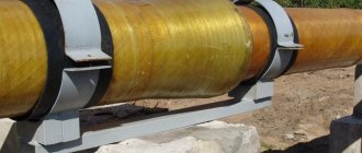
Fastening pipes on Y-Pipe cable hangers
- Allows you to quickly and easily hang two parallel pipes
- One mounting point for two pipes
- Replaces - supporting profile, crossbars and threaded rods
- Standard distance between pipes: 200 mm; 100 mm and 150 mm distances available on request
- The kit is ready to use without any preparatory work
- No on-site adjustment required
- The system is ideal for use with the universal clamp
- Supplied in kits, with cables of the required length