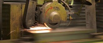
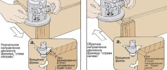
Features of flat grinding
The surface of the finishing disc determines the type of grinding: end or periphery. The main characteristics of peripheral grinding methods:
- mortise grinding. it is used when working with parts where the width is not greater than the height. also in cases where the plane is limited by tubercles. During this work, the disc wears out quickly, and this requires frequent adjustments. great accuracy is not achieved during this work;
- deep type of grinding. when carrying out such an action during the period of one table stroke at a low feed speed of the longitudinal type, full allowances are removed.
- grinding using variable cross feed. it allows you to finish any volumetric areas with high quality. If the transverse feed is inconsistent during the last movements, you need to set a small feed depth. this is required to reduce the inaccuracy that the disk creates as a result of wear;
- grinding using constant cross feed. it is carried out constantly, and its value for each movement should not be higher than half the circular height. If you compare this method with the previous one, it creates a more precise finish.
All of the above methods do not lead to contact between the wheel and the part to such a high degree as when finishing with an end face. As a result, there is no need to exert great physical effort, and not as much heat is generated during operation. Although the peripheral type is inferior in productivity to end finishing.
How to make a spring with your own hands from wire and in production
Design features of the machine
The main purpose of the 3G71 machine is grinding various parts and workpieces using special abrasive wheels. The process occurs with a spindle on which the abrasive is located. Changing the position of the part can occur due to the displacement of the work table and spindle head.
Basically, machining is carried out by contacting the periphery of the wheel with the workpiece being processed. With the help of special devices it is possible to change the angle up to 90°. However, to do this, you must purchase components that are not included in the standard equipment package.
The design and operational characteristics of the machine include the following:
- the electromagnetic plate ensures a stable position of the workpiece during processing;
- independent mechanisms for moving the work table and grinding head. The kinematic diagram of the latter is based on rolling guides;
- convenient location of feed response devices. They are located at the bottom of the worktable support. The control unit for the coolant supply system is also located there.
The control components are located in a separate block, which is installed on the right side of the equipment. During operation of the 3G71 machine, access to it remains free, regardless of the operating mode and position of the work table.
When installing additional components, it will be possible to perform profile grinding of workpieces. However, before this, it is necessary to agree on the dimensions and mounting locations of the device.
Send a file with your details and indicate what to invoice for.
PRELIMINARY APPLICATION FOR A MACHINE PASSPORT
Send a request, in the response we will indicate availability, price and other important information.
Response time usually takes from 20 minutes to 3 hours.
FEEDBACK
Send us your question and we will respond to your email within the next few hours.
We will be glad to hear any of your questions. We also look forward to your complaints, encouragement and suggestions.
CONTACTS
We are waiting for your call from Monday to Saturday from 09-00 to 20-00
And email and applications from the site around the clock!
More details on the "Contacts" page
SEARCH FOR A REGISTRATION PASSPORT
Search for the required passport for a machine or equipment in our database.
Enter the model of the machine or equipment for which you are looking for a passport.
Our database is constantly updated and contains more than 12,000 passport models, however, if you cannot find the documentation you need, submit a request and we will try to find the required passport for the machine or equipment.
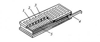
Components
The surface grinding machine has several important structural elements noted in the passport, which include:
- cross-type caliper;
- bed;
- column;
- table;
- longitudinal mechanical feed and reverse mechanisms;
- mechanical transverse feed and reverse mechanisms;
- grinding head;
- cooling system;
- mechanisms for automatic longitudinal and transverse tasks;
- distribution panel and hydraulic unit;
- electrical equipment;
- Lubrication system.
These elements create a single structure that allows for surface grinding.
Device Features
The 3G71 spindle has a horizontal arrangement. This arrangement determines that the cross-type table support moves on the frame. The movement is carried out along the rolling guides. During operation, it is possible to move the workpiece in two mutually perpendicular directions.
Circuit diagram 3G71
In any passport you can find the features of the cross table:
- The instructions indicate that the mechanized feed from a hydraulic cylinder works.
- During operation, you can use a manual or mechanical feed mechanism.
- Longitudinal movement of the workpiece also allows you to speed up the work process.
- The longitudinal reverse of the table and the transverse reverse mechanism also significantly increase the functionality of the model.
There is a control panel. The back side of the frame has a column; a 3G71 spindle moves along vertical guides, which belong to the rolling category.
Other design features include the fact that there is a hydraulic type unit inside the frame. Repair of the 3G71, namely the hydraulic system, can be carried out through the left door located in the frame. The system also has a special cooling tank, which is located on the right side.
Download the passport of the surface grinding machine 3G71
3G71 repair video
Main devices and movements
The diagram according to which the machine is assembled and its moves look like this. A column is attached to the frame. A cross support moves along the horizontal swing guides of the frame. The workbench also moves along with it, which performs longitudinal-translational moves backwards. The grinding head moves along the vertical guides of the column movement.
Rust remover for car body, bolts, pipes
On the inner lower side of the support on the GS 3e711v machine the following was fixed:
- cross feed reverse block;
- reverse block for longitudinal movement of the workbench;
- workbench longitudinal reverse block;
- workbench transverse reversal block;
- distribution panel;
- hydropanel.
The grinding spindle is assembled with preload, this is facilitated by high-precision radical-thrust bearings, which are lubricated with a “non-losing” lubricant. The hydraulic station on the RGS 3e711v is equipped with a volumetric control pump. Its scheme of action is to create a smooth regulation of the speed of movement of the workbench.
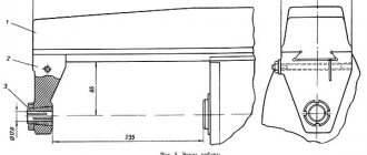
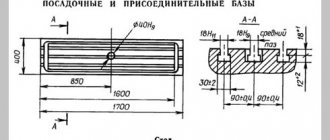
Installation drawing 3E711B
§6. PLANE GRINDING MACHINE 3E711V. Technical specifications.
Section: LIBRARY OF TECHNICAL LITERATURE Short path https://bibt.ru <<Previous page Table of contents of the book Next page>>
Surface grinding machines are classified: according to the location of the spindle - horizontal and vertical; according to the shape of the table - with a round and rectangular table. The main parameter characterizing surface grinding machines is the size of the table.
The 3E711B surface grinding machine with a rectangular table and a horizontal spindle is designed for processing flat surfaces of workpieces with the periphery of a wheel. Machine accuracy class B.
Technical characteristics of the machine 3E711B. Dimensions of the working surface of the table (length X width) 630×200 mm; speed limits for longitudinal movement of the table are 2-35 m/min; speed limits for transverse movement of the cross support 0.01-1.5 m/min; limits of vertical feed of the grinding head 0.001-0.09 mm; overall dimensions of the machine are 2700x1775x1910 mm.
Basic mechanisms and movements in the 3E711B surface grinding machine. Column B is attached to frame A (Fig. 125). Along the horizontal rolling guides of the frame, a cross support B with table D moves in the transverse direction, performing a longitudinal reciprocating movement. The grinding head G moves along the vertical rolling guides of column B. The frame contains mechanisms E and G for vertical and transverse feed, as well as the hydraulic drive of the machine.
Rice. 125. Kinematic diagram of the 3E711B surface grinding machine
Kinematics of the 3E711V machine. The grinding wheel receives its main movement from the electric motor M1 (N = 5.5 kW, n = 1500 min-1) through a poly-V-belt drive. Spindle II is mounted in multi-wedge bearings with self-aligning liners.
The transverse feed of the 3E711B cross support is carried out from the M2 DC motor (N = 0.25 kW, n = 30-3000 min-1) through helical wheels z = 34-100, z = 60-100 and lead screw VII.
When the M1 clutch is engaged in the wheel z = 100, automatic feeding occurs - continuous or intermittent for each table stroke (or double table stroke). To obtain intermittent feed when the table is longitudinally reversed, the M2 motor is given a command to turn on from a contactless travel switch.
Manual coarse and fine transverse feeds are carried out when the M1 clutch is turned to the left. A fine manual feed is obtained by rotating dial 2 through a worm pair z = 1-100; rough manual feed is carried out by handwheel 4 (the worm z = 1 is disengaged by handle 3).
The longitudinal feed of the table comes from a hydraulic drive; speeds are infinitely adjustable. Manual longitudinal feed is carried out by handwheel 1 with a built-in planetary mechanism. Satellites z = 18 and z = 19 roll around a stationary central wheel z = 19 and through another central wheel z = 20 the rotation is transmitted to the rack wheel z = 18 and the rack. The planetary gear significantly reduces the amount of movement per one revolution of the dial.
The vertical feed of the 3E711B grinding head is carried out from the M3 stepper motor at the moment of reversing the table or cross support. Rotation is transmitted to the lead screw XII with the M2 clutch engaged to the right through the wheels z = 34-100-100, the cardan shaft X, the engaged electromagnetic clutch M3 and the worm pair z = 1-30. Manual (coarse and fine) vertical feeds are carried out similarly to transverse manual feeds using handwheel 6 along dial 5.
The fast installation movements of the grinding head of the 3E711B surface grinding machine occur from the M4 asynchronous electric motor (N = 0.4 kW, n = 1500 min-1) with the M3 coupling disconnected.
Skip to navigation
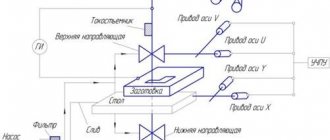
Operation of the hydraulic drive and interaction of components of the 3G71M grinding machine
The hydraulic drive of the machine is put into operation by pressing the “Start hydraulic drive” button, followed by setting the hydraulic panel valve 17 to the “Start” position. The oil flow, pumped by the vane pump 2, through the filter 4 through the pipeline 12 enters the central bore of the reversible spool 25 of the panel 17. When the spool 25 is positioned as shown in the diagram, the main flow enters the left bore and through the pipeline 18 into the hydraulic cylinder 20 of the table movement. The table moves in the direction of the arrow. Draining from hydraulic cylinder 20 occurs through pipeline 21 through throttle 14, valve II into hydraulic tank I.
The speed of movement of the table is regulated by throttle 14. The table moves to the right until the stop 19 associated with the table throws the reverse lever 23, which, through a system of levers, switches the control spool 24 to the left position. In this case, the right end chamber of the reverse spool is connected to pressure, spool 25 moves to the left, as a result of which the table reverses. Pipeline 21 becomes pressure, pipeline 18 becomes drain. The table moves in the opposite direction until the stop 22 moves the lever 23 to the reverse position.
The cycle is then repeated as described above.
Automatic vertical feed is carried out by turning on the electromagnet of the reversing spool 28.
The oil flow through pipeline 12 through the reversing spool and pipeline 27 enters the lower cavity of the torque hydraulic cylinder, from the upper cavity the oil through pipeline 26 through the spool and pipeline 29 is drained into the hydraulic tank. The flag is rotated clockwise. Through a gear system, rotation is transmitted to the vertical feed screw. The grinding head is fed vertically.
When the electromagnet is turned off, pipeline 26 becomes pressure, pipeline 27 becomes drain. The checkbox returns to its original position
Lubrication of the table guides and cross support, the vertical feed screw and guides and the cross feed screw is carried out from pipeline 13 through filter 10 and pipeline 15.
The oil consumption for lubrication of the table guides and cross support is regulated by throttle 16.
The oil supply for lubrication of the vertical feed screw and guides and the cross feed screw is turned on periodically by pressing button 9.
Excess oil coming from the table guides and cross support is drained through pipelines 7 and 8 into the hydraulic tank.
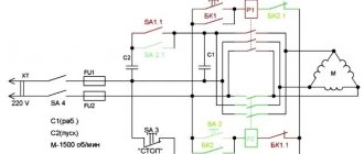
Features of the electrical circuit
The electrical circuit of this machine is as follows. The supply voltage is supplied by a copper wire (cross section 4 mm2). The power wires enter through a flange elbow located on the wall of the electrical cabinet on the right. The input wiring is led to a terminal block located on the wall of the electrical cabinet on the right. Then they are connected to the input block of the AK63-3M type circuit breaker. This electrical circuit is quite complex.
Electrical diagram 3E711B
The following is used on the machine:
- Power circuit -380 V.
- Control circuit -110 V; 29 V. DC indicator -24 V.
- Local lighting circuit – 24 V.
- Signaling circuit - 22 V.
- Electromagnetic tile circuit (constant indicator) -110 V.
Purpose and principle of operation of the surface grinding machine model 3G71
surface grinding metal cutting machine
The 3G71 surface grinding machine is mainly designed for grinding surfaces with the periphery of a wheel. On the machine, the end of the circle can be used to process surfaces located at an angle of 900 to the table mirror. Using various devices, profile grinding of various parts is possible. The accuracy of the profile depends on the method of threading the wheel profile and on the accuracy of the device used for fastening the part.
On a surface grinding machine, when working with the periphery of a wheel using the plunge method, you can perform rough and fine grinding of products whose width is less than the width of the wheel (Fig. 1.1, a), and fine grinding of products with profile surfaces of small width and profile depth (Fig. 1.1, b) . In this case, three shaping movements are required. The main rotational movement is communicated to the grinding wheel and determines the cutting speed. The grinding headstock is given a vertical feed to the depth of cut. Longitudinal movement by the feed amount is communicated to the table with the workpiece. When working with the periphery of a wheel with transverse feed, it is possible to perform rough and semi-finish grinding of products with sufficient rigidity, large depth of cut and small transverse feed (Fig. 1.1, c) and finishing grinding of heat-treated products with a small depth of cut and large transverse feed (Fig. 1.1, G). With this processing method, four movements are required because a cross feed is added. Four movements are also necessary when grinding surfaces located at an angle of 900 to the table mirror with the end of the wheel.
The machine can also process the shaped surface of products in non-profiled sections (straight sections) and profiled sections (curved sections) in a circle (Fig. 1.1, e) using a sine vice, magnetic rotary plates, dividing devices, etc.
Rice. 1.1 — Schemes of processing on a surface grinding machine
Purpose and scope
Descriptions of the machine in question can be found quite often. It is used for grinding surfaces using the peripheral part of the wheel. It is possible to treat a surface that is located at right angles to the base. The characteristics can be significantly expanded if necessary.
The equipment in question allows for profile grinding. Technical characteristics determine that the method of threading the wheel profile affects the ability to process a particular shape, and also affects the accuracy of the resulting dimensions.
Often, the design of a surface grinding machine includes an electromagnetic plate, which is used to fasten the workpiece.
Key features that influence the scope of application are indicated in the data sheet. These include:
- The accuracy that can be achieved is class B.
- Roughness of the processed surface V 10.
Hydraulic diagram 3G71
The scope of application is very wide. You can often find it in large-scale production factories. The model is simple to operate; the control circuit allows precise control of the processing process.
Power supply system for electrical equipment of the 3G71M machine
The machine is connected to a three-phase alternating current network with a voltage of ~380 V, a frequency of 50 Hz.
- Asynchronous squirrel-cage electric motors M1-M3, M5, M6, M8 and transformer TP3 are supplied with a voltage of 380 V alternating three-phase current.
- The electric motor M7 is supplied with a voltage of ~220 V alternating three-phase current, taken from the transformer Tr3.
- The control circuit and electromagnet EM1 are supplied with a voltage of ~110 V AC from transformer Tr2.
- The local lighting bracket LI is supplied with ~24 V AC voltage from transformer Tr2.
- The signaling equipment L2 and L3 is supplied with a voltage of ~5 V AC from the transformer Tpl.
- The electromagnetic device is supplied with 110 V DC voltage through the rectifier D11. The DC control circuits operate from the voltage taken from the D10 rectifier, the input of which is supplied with a 36 V AC voltage from the Tpl transformer.
- The contactless limit switch VB2 is powered by a constant voltage taken from the rectifier D26, the input of which is supplied with a voltage of 31 V from the windings of the 36 V and 5 V transformer Tpl, connected in opposite directions.
Electrical equipment of surface grinding machine 3G71
The electrical equipment of the machine contains:
- asynchronous squirrel-cage electric motors:
- grinding wheel drive (MZ) 2.2 kW, 2860 rpm, 220/380 V, 50 Hz, AOL2-22-2-S1
- hydraulic drive (M4) 1.1 kW, 930 rpm 220/380 V, 50 Hz AOL2-22-6-S1;
- electric cooling pump (M1) 0.12 kW, 2800 220/280 V 50 Hz, PA-22;
- magnetic separator drive (M2) 0.08 kW, 1390 rpm, 220/380V, 50Hz, AOL 012-4-S2;
- drive for rapid movement of the grinding head (M5) 0.18 kW, 1400 rpm 220/380 V
- electromagnetic plate (EMP1) NOV, 08A, EP-21G;
- rectifier block (D1) 75GM24Ya-K2;
- control equipment;
- alarm and lighting equipment;
- protection equipment.
The machine is designed for connection to a three-phase alternating current network 380 V, 50 Hz.
The circuit is powered as follows:
- asynchronous squirrel-cage electric motors Ml, M2, MZ, M4, M5 are supplied with a voltage of 3-50 Hz, 220/380 V; the control circuit receives power 110 V, 50 Hz;
- 110V DC voltage is supplied to the electromagnetic plate EMP1 from the selenium rectifier D1;
- voltage is supplied to the input of rectifier D1
129 V from transformer Tp1;
the local lighting lamp JI3 is supplied with a voltage of 24V, 50Hz from transformer Tp1; signal lamp L1 is supplied with 5V AC voltage from transformer Tp1
Note. The description of the operation of electrical equipment is compiled for a 110V control circuit.
The electrical circuit of the machine provides the following operating modes:
- working with an electromagnetic cooker;
- work without an electromagnetic plate.
The machine is turned on by turning the input packet-cam switch BI1. Voltage is supplied to the power circuits and control circuit.
The signal light L1 on the machine control panel lights up.
When working with an electromagnetic plate, switch B2 is set to the “With plate” position, voltage is supplied* to the selenium rectifier D1, contact 11-12 of switch B2 is closed, and contact 11-5 is opened. If the electromagnetic plate EMP1 is connected to connector Ш2, and the switch ВЗ is in the “On” position, then the electromagnetic relay РЗ is turned on, which, with its contact 11-5, allows the start of the hydraulic drive and the grinding wheel.
By pressing the KH2 button, the magnetic starter P2 is turned on, which supplies voltage to the hydraulic drive electric motor M4.
By pressing the KN1 button, the magnetic starter P1 is turned on, which supplies voltage to the electric motor of the grinding wheel MZ, and through connector Ш1 to the electric motor of the cooling pump M1 and the magnetic separator M2. The M4 hydraulic drive electric motor is stopped by pressing the KNZ button, which opens the power circuit of the P2 starter coil at points 7-4. Button KH4 is used for general stop of the machine.
By turning the handle of the reversing drum switch B5 (with self-return) to the left or right, the electric motor M5 is turned on, which accelerates the movement of the grinding head up or down.
When working without an electromagnetic plate, switch B2 is set to the “Without plate” position, the power circuit of the electromagnetic plate is opened, and contact 11-5 bypasses the open contact 11-5 of the electromagnetic relay
Otherwise, the operation of the machine does not differ from that described above. Blocking the sudden shutdown of the electromagnetic plate EMP1 is carried out by electromagnetic relays RZ, the closing contact of which at points 11-5 opens and de-energizes the coils of magnetic starters P1 and P2. Electric motors M1, M2, M3 and M4 stop.
Protection of electric motors M1, M2, MZ, M4, M5 and control circuits from short circuit currents is carried out by fuses PR1, PR2, PRZ, PR4, PR5.
Protection of electric motors MZ and M4 from overloads is carried out by thermal relays RT1 and RT2.
Zero protection is carried out by coils of magnetic starters P1, P2.
The machine must be grounded to the general workshop circuit in accordance with existing rules and regulations.
Otherwise, the operation of the machine must be carried out in accordance with the “Rules for technical operation and safety of servicing electrical installations of industrial enterprises.”
Information about the manufacturer of the surface grinding machine 3E711B
Manufacturer of the surface grinding machine 3E711B Orsha machine tool plant Krasny Borets, founded in 1900.
In 1959, the plant began production of high and especially high precision surface grinding machines.
In 1967, the 3711 surface grinding machine was released, the first metal-cutting machine of particularly high precision in the USSR.
The 3E711V high-precision universal surface grinding machine with a horizontal spindle replaced the outdated 3G71 machine.
Principle of operation
The main difference between this type of mechanism and emery machines is the level of processing of the workpieces. It is suitable not only for sharpening cutting devices, but also for removing unnecessary layers of material.
Physically, the machine is equipped with a power mechanism (electric motor). Due to transmission elements (belt or gear drives), the grinding shaft rotates. To securely fix the workpieces, a base is provided, often attached to the mechanism body.
Depending on the design features, processing mechanisms can be of the following types:
- position of the working body - vertical or horizontal spindle. This directly affects the processing technique;
- accuracy when removing unnecessary layers. For production modifications this is tenths of a micron. In homemade machines, it is very difficult to obtain such parameters;
- mobile organ To process large parts, the location of the grinding element or the part itself can be changed. In the second case, there is a need to equip it with a moving table.
To make a surface grinder with your own hands, techniques with manual settings are used. Despite the rather significant errors, they are distinguished by ease of execution.