With the advent of mechanical gears, the need arose to convert rotational speed. Some mechanisms need to increase it, others need to decrease it. Mechanical devices that increase output speed at the same time as transmitting and decreasing torque are called multipliers. Most often they are produced in the form of separate units with gears of various types. Used in machines in which the motor shaft does not rotate at sufficient speed to perform a particular operation.
Gearbox increases speed by 3 times
How does a multiplier differ from a reducer?
Quite rarely, but it happens that a client is interested in a gearbox that increases speed. It would be a stretch to call such a mechanism a gearbox, since it has a precise definition - a multiplier. So, let's look at what the difference is between them.
A lot has been written about gearboxes, and I don’t want to repeat myself. Let me just remind you that the gearbox increases torque by reducing the input rotation speed, i.e. converts angular velocity into "newtonometers".
Fundamental differences between a multiplier and a gearbox.
The multiplier is also a kind of gearbox, but with a gear ratio of less than 1, i.e. increasing output speed by reducing input torque. For clarity, you can bring a bicycle, where the multiplier is located in the form of a chain drive. As a result, it would be logical to define the concept that a multiplier is a reverse gearbox. Some gearboxes, both worm and cylindrical, with a small gear ratio allow reverse gear in practice, but this is not provided for by the operating conditions and removes all responsibility from the seller and manufacturer. We would not recommend using any gearbox from our catalog as a multiplier.
Historical information: one of the first multipliers is an ordinary village spinning wheel. The small revolutions of the large wheel created by the pedal drive are converted into large revolutions of the spindle. The gear ratio of this design is determined by the ratio of the spindle diameter to the wheel diameter, which is significantly less than unity.
Currently, many owners of home workshops equip them with modern tools and equipment, which, being highly efficient and easy to use, significantly facilitates work and increases its productivity. However, at the same time, quite technically simple devices that can be made with your own hands in a home workshop are still in demand. One of them is a reduction gearbox.
What is a reduction gearbox?
It is a special type of mechanism that serves as a transmission link between devices in which the active parts perform rotational motion. It is often used to transmit and convert torque from the unit that produces it to the device that uses the mechanical energy supplied to it. Unlike other types, a reduction gearbox provides a reduction in the number of revolutions and an increase in torque.
A reduction gearbox consists of a housing, gears, transmission chains, a worm mechanism, and shafts, with the help of which torque is transmitted and converted.
Toothed gears are located on the shafts in a rigid coupling, and worm gears are attached. They ensure the transfer of motion to each other, during which its transformation is carried out.
There are different types of reduction gearboxes:
In addition, they are:
Basic indicators
- efficiency;
- transmission power;
- number of rotations of the driven and drive shafts.
The reduction gear has a fairly simple design, so if you have the appropriate spare parts and materials, you can make it in a home workshop with your own hands.
Preliminary preparation
Before you begin creating this device, you must have general knowledge of mechanics, be able to use repair tools and equipment, and know the operating principle and structure of this unit.
In addition, you need to initially determine:
- the type of future gearbox and its version;
- the gear ratio that will need to be converted and determined at the output;
- indicators of dynamic loads that will affect the working parts of the device;
- weight and dimensions of the future device;
- installation angle;
- temperature limits that will occur in the device during its operation;
- switching cycle – full or variable;
- intensity of operation.
Parts and parts of the reduction gearbox
- Drive and driven shafts;
- Bearings suitable in diameter for axles and shafts;
- Sets of sprockets of a certain size with a certain number of teeth;
- Torque transmission chains;
- Sheet steel;
- Corner profile;
- Frame.
More details about the components
The assembly process is not as complicated as the selection or production of spare parts necessary for such a gearbox.
- Device body. In industry it is produced by casting. The necessary holes are made using high-precision equipment, since it is necessary to achieve the mutually correct arrangement of the shafts and the alignment of the stars. When producing it, it is necessary to make the top cover removable. This will facilitate and simplify the process of servicing it during operation;
- Shafts and axles of the gearbox. They support gears and are used if they need to be equipped with this device. Installation is carried out by pressing onto splines or keys. For their manufacture, it is better to use durable steel measuring from 10 to 45 mm, which is easy to machine;
- Bearings. They are used as supports for shafts and resist loads and provide the possibility of rotational movement. Its reliability, durability and performance depend on the correct selection of these gearbox elements. If you are installing spur gears, then it will be sufficient to install conventional single or double row ball bearings. If a helical bearing or worm gear will be installed, then a roller or angular thrust ball bearing will be the best option. It is better to buy new ones than to use them from disassembly;
- Gears. They provide a change in the rotation speed of the shafts and, naturally, a reduction in the gear ratio. For their production, special metal-cutting equipment is used, which home workshops are not equipped with. The dimensions and characteristics of other parts included in this unit, as well as the distance between the axles and shafts, depend on the size of the gears. When installing, it is important to correctly set the gap between them. I-20 oil is perfect for lubricating gears. It is filled to the level of the bottom of the gears. Other parts of the device are lubricated by spraying lubricant onto them. You can take it from disassembly or buy new ones;
- Oil seals. They prevent oil from leaking out of the device body. They are installed at the exit points of the shafts on bearings under the covers. Are bought;
- Safety coupling. It is designed to prevent destruction of the device when excessive loads occur. Buyable;
- Bearing caps. They can be different - deaf and through. Designed to facilitate maintenance and installation of bearings. You can grind them yourself or find them at a disassembly site.
Tool
To make a reduction gearbox you will need the following tool:
- screwdrivers and wrenches;
- drill;
- needle files;
- inverter welding;
- ruler;
- pliers;
- calipers;
- hammer;
- vices and others.
Stages of work to create this device
- Installation of drive sprockets on the input shaft. In this case, installation can be done by spot welding, flange or key connection;
- Assembly of driven shaft axles;
- Installation of the driven sprocket;
- The case can be picked up from disassembly and adjusted or made by yourself. At the same time, it is necessary to make technological holes in it for oil seals and bearing connections;
- Installation of closed type ball bearings. An excellent option would be cylindrical ones. Their installation is carried out by tension;
- The drive shaft is mounted on eccentric bearing supports with the ability to adjust the chain tension by at least 15 degrees;
- At the final stage, a lid with a sealing gasket is installed.
Having decided to do this, it is better to first assess your strengths, knowledge and skills in handling the tool, so as not to get into trouble by spending a decent amount of money, a lot of time and effort, and at the same time, without creating the necessary device, but if you are an existing or former mechanic, you can safely get down to business.
Featured Posts
Create an account or log in to comment
You must be a user to leave a comment.
Create an account
Register for an account. It's simple!
To come in
Already registered? Sign in here.
There are currently 0 users on the page
There are no users viewing this page.
vi-pole.ru
Operating principle
Cylindrical gears have internal and external gearing with different slopes; straight and helical gears are used. Strength is increased by the contact area of the oblique teeth. The slope angle is limited to 20 degrees. In bevel mechanisms, the shafts most often intersect at an angle of 90°, which increases the level of permissible load.
- capable of transmitting high powers;
- compact;
- rotate quickly;
- have constant gear ratios
- have high efficiency.
The movement is transmitted harshly, the operation is noisy, and lubrication is required frequently.
Worm mechanisms transmit motion between axes located at an angle of 90°. The wheel speed differs from the worm speed, which reduces efficiency and accelerates wear. The performance can be improved by using in the manufacture of pairs of materials that differ in anti-friction characteristics (steel paired with bronze, cast iron, brass).
- have considerable gear ratios;
- operate silently and smoothly;
- equipped with a self-braking function;
- have high kinematic accuracy.
The disadvantages include the need for expensive materials, rapid wear, and low efficiency.
Flexible links (ropes, belts, cords, tapes, chains) are used in mechanisms in which it is necessary to transmit movement at a distance. The gear ratio can be variable or constant, the value changes smoothly or stepwise.
Transmissions with belts are round, V-belt and flat belt.
- silent operation;
- the ability to transmit movement over relatively long distances;
- the presence of additional protection due to the elasticity of the belt;
- ease of operation.
Mechanisms with belts are large, slippage disrupts operation, the load on the shafts increases, and belts need to be changed frequently.
The operation of a chain drive is based on the interaction of sprockets and chain.
- lamellar gear;
- sleeve rollers;
- bushing.
The first provide the smoothest operation, the second are relatively heavy, but wear out slowly, the third are light, but require frequent replacement due to wear.
Chain drives can withstand heavy loads, do not slip or slip, but they are noisy, the chains wear out quickly, and lubrication is often required.
Friction mechanisms differ in the location of the shafts (parallel at an angle), type of contact (internal, external), and adjustability.
DIY production, advantages and disadvantages of the device
Mechanical devices of different types
The use of wind generators in conditions of weak and moderate winds, typical for most regions of Russia, creates special requirements for the rotor design. At low flow rates, the windmill impeller rotates too slowly to generate sufficient electricity.
It is almost impossible to increase the rotation speed of a windmill.
The use of more sensitive types of impeller has little effect on the speed; only the possibility of starting from a weaker wind changes, which does not give a significant effect. To solve the problem, different types of mechanical devices are used - gearboxes .
What is the gearbox used for?
The optimal generator rotor speed for generating electric current is about 2000 rpm. There are also less high-speed types of generators, but in any case, for high-quality operation, the wind wheel must give the generator rotor a sufficiently high speed. Existing conditions rarely allow high values to be obtained.
In winds of 6-8 m/s, the rotation speed of the wind wheel is not capable of ensuring the nominal operating mode of the generator, which reduces the efficiency of the entire set.
The solution to the problem is to install a gearbox between the impeller and the rotor of the overdrive generator. It increases the rotation speed of the generator due to a single or multi-stage increase in rotation speed, for which a pulley system or planetary (differential) type device is used.
When using a gearbox, one rotation of the impeller accounts for several revolutions of the generator shaft. If the gearbox design is multi-stage, then the gear ratio can be increased tens of times, although this is fraught with loss of power.
It must be taken into account that the gearbox allows you to obtain a high rotation speed due to a sharp (proportional to the gear ratio) drop in power on the shaft. To achieve high speed in this case means losing the force that allows you to initiate rotation of the rotor, move the tight shaft from its place, and overcome sticking magnets.
It is not advisable to use gearboxes with a large gear ratio for wind generators, since the performance of the complex suffers from the loss of power.
Peculiarities
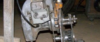
The simplest option is to use two pulleys with different diameters . One, larger one, is installed on the wind wheel shaft. It, through a V-belt transmission, transmits rotation to a smaller pulley mounted on the generator shaft. The rotation speed increases by an amount proportional to the ratio of the pulley diameters.
Such a transmission can have several stages, for example, from the wind wheel shaft to the intermediate pulley, and from there to the generator pulley. Each gear gives an increase in rotation speed, but reduces power in proportion to the gear ratio. This can negatively affect the operation of the generator - a weak force on the shaft will not be able to force it to start rotating, overcome sticking and other resistance of the rotor.
The gearbox option with a V-belt drive is the simplest and most reliable; it can be manufactured and assembled independently.
A more complex type of gearbox that cannot be manufactured independently is planetary. It is a gear system consisting of:
- ring gear (epicycle), which is a circle with teeth directed inward. Its diameter is the largest; all other gears are located inside. It receives the initial torque and transmits it sequentially
- satellites are gears of relatively small diameter that mesh with the central (final) gear or with other satellites
- the carrier is a circle on which the axes of the satellites are located
- sun (central) gear. It receives the impulse from the satellites, rotating at a speed determined by the gear ratio
Planetary gearboxes are highly compact; the absence of open parts eliminates the risk of element failure. Metal parts are protected from corrosion, the possibility of any failures or malfunctions is minimal. At the same time, it is extremely difficult to make a homemade planetary gearbox, and it is quite expensive to purchase.
For use on horizontal wind generators, a planetary gearbox is preferable, since it is more reliable, more compact and does not require constant maintenance, while homemade V-belt devices constantly experience some kind of failure (belts break, shafts get jammed and other problems).
Advantages and disadvantages
The use of gearboxes allows us to solve the problem of low speeds and ensure the functioning of the generator in nominal mode. At the same time, everything is somewhat more complicated than it seems at first; the use of gearboxes has many advantages and disadvantages . Let's take a closer look at them.
The advantages of gearboxes on a wind wheel include:
- the ability to significantly increase the rotation speed of the generator
- reducing the kit’s dependence on existing meteorological conditions
- if necessary, you can change the operating mode of the device, optimally prepare it for working with this equipment and wind flows
The disadvantages of gearboxes are:
- loss of power on the shaft, creating problems when starting the generator
- difficulties arise in overcoming the resistance of magnets, sticking
- the dimensions of the device create an additional barrier to the wind flow, causing unnecessary noise
- the load on the wind generator mast increases
- servicing a gearbox located at height is extremely difficult and dangerous.
- There is no possibility of high-quality repairs without lowering the mast
You can see that there are more disadvantages than advantages. They are not very important in terms of importance, but in some situations they are insurmountable. For example, if the impeller does not allow you to develop more power, then using a gearbox will finally weaken the shaft and prevent it from starting the generator. The solution to the problem is to change the size of the wind wheel, allowing to obtain sufficient axial force.
DIY assembly
Making your own gearbox will require some tools and materials. First of all, you should decide on the type of design that will best suit your existing generator. To do this, you need to calculate how much you need to increase the rotation speed, and decide on the material and technical base.
The main element of a homemade gearbox is pulleys for a V-belt drive. It is recommended to use the V-belt version; it is much more reliable and efficient than the flat-belt version.
You can use ready-made pulleys, or order production from a turner. In this case, you can get the most preferable option for increasing speed.
The generator pulley can be mounted directly on its shaft, while the impeller pulley can most easily be mounted on the base of the hub. You just need to secure the generator to the base and make a tensioning device to ensure high-quality adhesion of the belt to the pulleys. You shouldn’t be too zealous with the tension, as this increases the resistance to rotation and creates a braking force on the wind wheel.
The device with one gear is the simplest and does not require additional installation of hubs and other elements. If you plan to use two or more stages, then the installation of additional hubs, shafts and pulleys will be required. At the same time, it is not recommended to use more than 2 stages; this can completely deprive the generator shaft of the ability to rotate - it will stop at the slightest impact.
recommended products
energo.house
Areas of application
Multipliers are used in:
- construction (as part of tools that increase torque and assembly and disassembly of threaded connections);
- oil, gas and mining industries;
- aerospace and petrochemical industries;
- in mechanical engineering;
- in the production of lifting mechanisms, ropeways;
- during the construction of metal structures and bridges;
- in car and aircraft manufacturing;
- electric power industry.
When choosing the type of multiplier, it is advisable to get advice from a technical consultant. Tell him the requirements for the mechanism and data on operating conditions. If necessary, a specialist can visit the enterprise to delve deeper into the work and suggest the best model.
angular gearbox that increases speed by 3 times
angular gearbox that increases speed by 3 times
>
Do-it-yourself booster gearbox for a homemade oil station - youtube Cancel month free booster gearbox for a DIY oil station ivan s loading two-stage gearbox with centrifugal clutch - duration 3 13 box647 65 940 13 refilling camping cylinders - saving money - duration 1103 igor negoda 4 035 607 gearbox for a wind generator - duration 914 oleg melnikov 6,793 views 914 hydroelectric 11000 rpm - crazy worm - duration 2157 maxim medvedev 13,356 After the first rides with the converted classic gearbox, it became clear that the quad was moving slowly, the idea came to put a step-up gearbox 2 in front of the rear gearbox, 51 and in front of the front 251 with the front end disconnected, to start from scratch, a gearbox was made, assembled and installed in front of the rear gearbox Do-it-yourself step-up gearbox - special equipment Homemade bevel gearbox with your own hands step-by-step assembly process First of all, you will need to calculate the rated power pn pn re ls x fs where you will be able to find out the correct type of bevel gear angle and you will also need to calculate the number of revolutions per minute and torque, for example, the idle speed of your motor 10 is 600 rpm, the required wheel axle revolutions for a speed of 3 mph are 200 rpm, respectively, your gearbox for a walk-behind tractor must have a gearbox ratio 31, the rotation speed of the axis is reduced by 3 times, in relation to the speed of the motor shaft, accordingly, the torque increases threefold; we determine the type of gearbox. Gearboxes and step-up boxes bezares for equipment and hydraulic pumps. Splitter gearboxes sb 118, sb 154 gearbox step-up box with two outputs with many combinations. outputs for pump and flange available gear ratios 118, 154 model sb 118 sb 154 gear ratio 1118 special booster box for simultaneous operation of three hydraulic pumps code 608099 max torque nm 600 max power 1000 rpm 63 kW All about gearboxes - the gearbox is designed to reduce the angular speed rotation and increase in torque And since the angular speeds of the engine shaft and the drive shaft of the working machine, as a rule, are not equal to each other, for coordination in a mechanical drive, a transmission mechanism is used, consisting of a set of mechanical gears. A gear drive is one of the most common types of modern mechanical systems for general industrial application, the gearbox is designed to reduce the angular speed of rotation and increase the torque; the load capacity of the gear transmission of a 6ts type gearbox is 1.3 -1.5 times higher compared to an involute analogue with the same gear ratios of gearboxes of the 6ts2 and 1ts2u series, the rated torque on the output shaft for 6ts2-160 is 4000 nm, and for 1ts2u-160 only 1250 nm Boost gear - do it yourself diy - korean random forum Each tier will double the speed, that is, the total increase in speed is 16 times I switched from 3 ds max to sapr compass 3 d I made one pair of gears, the first one has 12 teeth, the second one has 24 teeth. I made the manual gearbox only once and didn’t bother stupidly using a spinning fishing reel for 16 was enough for me. Calculate a reduction gearbox that increases the force by 10 times - for nothing teachers - metal forum He capable of lifting a load on a string weighing 120g; it is necessary to lift a load weighing 1200g; the task is to calculate a reduction gearbox that provides the greatest efficiency. As far as I understand, to increase the force, it is necessary to transfer the force from attention due to the uncontrollably multiplying video bloggers; placement of videos in topics is limited; Gearbox for a windmill made by oneself hands, advantages and disadvantages of the device How to choose a gearbox for a windmill, a complete list of the properties and characteristics of the device, as well as its use and assembly with your own hands at home, it increases the rotation speed of the generator due to a single or multi-stage increase in the rotation speed, for which a system of pulleys or planetary differential type devices when using a gearbox, one rotation of the impeller accounts for several revolutions of the generator shaft; if the gearbox design is multi-stage, then the gear ratio can be increased tens of times, although this is fraught with loss of power, it must be taken into account that the gearbox allows you to obtain a high rotation speed due to a sharp proportional to the gear ratio of the drop in power on the shaft Answersmailru Is it possible to increase the speed and strength of the engine due to the gearbox? The power cannot be increased in any way by the law of conservation of energy the speed can be increased either by speed or by power, choose the law of conservation of energy the third option does not provide for in this case when the speed increases it will decrease slightly torque and the engine was 4 kW, and will remain 4 kW until it is replaced by 7.5 kW
angular gearbox that increases speed by 3 times
angular gearbox that increases speed by 3 times. Answersmailru Is it possible to increase engine speed and power using a gearbox?
Transmission gearboxes impresa ltd. All about gearboxes - the gearbox is designed to reduce the angular speed of rotation and increase torque
angular gearbox that increases speed by 3 times.
Angular and parallel gearboxes comer srl. Gearboxes and booster boxes bezares for machinery and hydraulic pumps
angular gearbox that increases speed by 3 times. Do-it-yourself gearbox for a windmill, advantages and disadvantages of the device
angular gearbox that increases speed by 3 times. Gearboxes and booster boxes bezares for machinery and hydraulic pumps
angular gearbox that increases speed by 3 times. Step-up gearbox - do it yourself diy - korean random forum
Angular reduction gearbox, step-up gearbox 2463 2,500 UAH - other bridge - ads for free 12806510. Gearboxes and gearboxes bezares for equipment and hydraulic pump
angular gearbox that increases speed by 3 times. Gearboxes and booster boxes bezares for machinery and hydraulic pumps
angular gearbox that increases speed by 3 times. Do-it-yourself gearbox for a windmill, advantages and disadvantages of the device
angular gearbox that increases speed by 3 times. Do-it-yourself booster gearbox for a homemade oil station - youtube
angular gearbox that increases speed by 3 times. Calculate a reduction gearbox that increases the force by 10 times - teachers for nothing - metal forum
angular gearbox that increases speed by 3 times. All about gearboxes - the gearbox is designed to reduce the angular speed of rotation and increase torque
angular gearbox that increases speed by 3 times. Answersmailru Is it possible to increase engine speed and power using a gearbox?
Angle multipliers comer lf-140j, lf-140a.
angular gearbox that increases speed by 3 times. Calculate a reduction gearbox that increases the force by 10 times - teachers for nothing - metal forum
angular gearbox that increases speed by 3 times. Calculate a reduction gearbox that increases the force by 10 times - teachers for free - metal forum Angular and parallel gearboxes comer srl. Do-it-yourself gearbox for a windmill, advantages and disadvantages of the device
angular gearbox that increases speed by 3 times. DIY booster gearbox - special equipment
Angular and parallel gearboxes. Do-it-yourself booster gearbox for a homemade oil station - youtube
Gearboxes and multipliers with parallel shafts comer mr-90. Calculate a reduction gearbox that increases the force by 10 times - teachers for nothing - metal forum
angular gearbox that increases speed by 3 times. All about gearboxes - the gearbox is designed to reduce the angular speed of rotation and increase torque
News. Gearboxes and booster boxes bezares for machinery and hydraulic pumps
angular gearbox that increases speed by 3 times. Gearboxes and booster boxes bezares for machinery and hydraulic pumps
angular gearbox that increases speed by 3 times. DIY booster gearbox - special equipment
Answersmailru Is it possible to increase engine speed and power using a gearbox? A gearbox that increases speed by 3 times is angular
gearbox that increases speed by 3 times angular Answersmailru Is it possible to increase engine speed and power using a gearbox?
Answersmailru Is it possible to increase engine speed and power using a gearbox? A gearbox that increases speed by 3 times is angular
xvtkju.reductor.ru.net
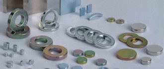
Types of multipliers
Like other gear mechanisms, multipliers are divided into types depending on the type of transmission used:
- cylindrical – characterized by high efficiency (up to 98%);
- worm - the drive is connected to the worm shaft;
- planetary – compact, withstand increased loads;
- conical - change not only the speed of rotation, but also its direction.
Based on the number of stages, converters are divided into one-, two-, three- and multi-stage.
Recommendations for selection
How to choose a gearbox instead of a broken one, for existing equipment and when creating mechanisms yourself. The main thing is the power on the output shaft. It is calculated based on engine speed by gear ratio.
You should pay attention to the location of the shafts; in cylindrical models it can be in one direction.
Fastening is carried out using a flange directly to the motor shaft and is installed on the platform using holes in the sole.
The marking indicates the center-to-center distance between the shafts. This size has a design significance when installing the unit and connecting it to the engine and the shaft of the working mechanism.
You should look at which pair is the first in the gearbox, its gear ratio, gearing. The choice of gearbox also includes the location of the shafts in space. They can be located at right angles and be in different planes. The type of bearings is indicated in the technical documentation. There is also a table of service life of different components.
When designing a machine, the selection of a worm gearbox is carried out based on power and gearing location. With lower engagement, the pair is well lubricated, does not require additional cooling and can operate for a long time. You should pay attention to the operating mode. The node is not always able to work for several hours continuously. The worm joint overheats quickly.
conclusions
Thus, a multiplier is a device that increases the angular speed of a shaft and has a gear ratio of less than 1. The 1Ts2U helical gearbox, on the contrary, reduces the angular speed, increasing torque. The gear ratio of the mechanism is from 8 to 50. Accordingly, this type of converter cannot in any way be used as multipliers.
On the website you can buy 1Ts2U gearboxes for their intended purpose. Cooperation with us is an opportunity to purchase high-quality equipment without overpaying. The warranty on converters is 12 months.
Source
What types of walk-behind tractor gearboxes are there - description and features of the mechanisms
The gearboxes that modern walk-behind tractors are equipped with are divided among themselves according to their purpose. The following types of built-in mechanisms are distinguished:
- angular gearboxes - the role of this equipment is to connect the installed motor and the walk-behind tractor transmission not connected to it. This mechanism is known for its efficiency and optimal cost. If necessary, the angular gearbox for the walk-behind tractor can be modified to increase the endurance and power of the element. Another important advantage is the simple design of modern angular gearboxes for walk-behind tractors. The simple design of the mechanism allows you to assemble it yourself without spending money on expensive parts;
- reduction gearboxes - equipment of this type is designed to reduce the number of generated revolutions in order to repeatedly increase the power of the walk-behind tractor. The reduction gearbox for the walk-behind tractor built into the design of the unit operates under the control of a separate air cooling system, which guarantees uninterrupted operation of the mechanism when working in the most difficult weather conditions. Motoblocks with such gearboxes have high endurance and versatility;
- Gear reducers - the advantages of these mechanisms include fairly high gear ratios, reliability, high wear resistance and simplicity of design, which allows them to be quickly repaired without outside help. The gear reducer is very easy to use and self-maintenance;
- reverse rotation gearboxes - the operating principle of such mechanisms is called the “reversal circuit”, and gives the walk-behind tractor a lot of advantages. The main one is the ability to move at reverse speed, which significantly increases the maneuverability of the unit. Experts consider the main disadvantage of such gearboxes to be their low performance when using heavy attachments;
- worm gearboxes – the worm gearbox is made mainly from durable materials, due to which it has good characteristics and wear resistance. It shows high reliability, regardless of operating conditions.
The simplicity of the design of a modern gearbox allows you to independently manufacture such a mechanism for a household walk-behind tractor. By adhering to the correct procedure and having all the necessary materials available, the farmer will be able to make a homemade unit, which in terms of reliability and quality will be practically not inferior to its market counterparts.
Varieties
The gearboxes with which walk-behind tractors are equipped seem identical only at first glance. In fact, these devices can be divided into three groups. The differences lie in the design features of the gearboxes. Let's get to know the representatives of this family in more detail.
Angular
Angle-type gearboxes are elementary structures that serve to connect the transmission to the power plant of the unit.
Due to the absence of complex components, some farmers install homemade versions of angular gearboxes on walk-behind tractors.
The structure of this node looks like this:
- Mechanism body.
- Belt drive pulley with fastening.
- Rotor shaft.
- Flange complete with mounting and bearing.
- Washer and fixing key.
Gear
This is a more complex mechanism, which is impossible to recreate at home without special skills and knowledge.
Gear reducers are called reduction gearboxes. Thanks to its design features, the mechanism reduces the engine speed, simultaneously increasing the power output of the walk-behind tractor.
Such gearboxes have a long service life, so they are suitable for performing various jobs, and do not suffer mechanical damage even under peak loads.
Unlike angular models, reduction gearboxes require additional cooling.
Asynchronous motors with wound rotor
The main way to control an IM with a wound rotor is to change the amount of slip between the stator and the rotor.
Voltage regulation
Through special LATR autotransformers, by changing the voltage on the motor windings, the shaft speed is adjusted.
This method is also suitable for IMs with a squirrel-cage rotor.
In this way, it can be adjusted from the minimum to the nominal parameters of the engine.
Installing active resistance in the rotor circuit
A variable rheostat or set of resistances in the rotor circuit affects the rotor current and field. Thus changing the amount of slip and the number of engine revolutions.
The greater the resistance, the less the current, the greater the sliding value of the blood pressure and the lower the speed.
Mechanical devices of different types
The use of wind generators in conditions of weak and moderate winds, typical for most regions of Russia, creates special requirements for the rotor design. At low flow rates, the windmill impeller rotates too slowly to generate sufficient electricity.
It is almost impossible to increase the rotation speed of a windmill.
The use of more sensitive types of impeller has little effect on the speed; only the possibility of starting from a weaker wind changes, which does not give a significant effect. To solve the problem, different types of mechanical devices are used - gearboxes .
Worm gear reversibility
This parameter determines whether the input shaft can rotate when a certain torque is applied to the output shaft.
The reversibility of a worm gearbox depends on numerous factors, including helix angle, gear ratio, lubrication, temperature, worm surface finish, vibration, etc.
The reversibility of a worm gearbox directly depends on the efficiency (static or dynamic).
The ability to do this and the force at which this happens determines the degree of reversibility of the gearbox
When using a gearbox to move loads, high reversibility prevents inertia of moving parts, which avoids peak load on the drive
In the case of using a gearbox for lifting loads, high irreversibility is selected in the absence of a brake on the motor shaft. ATTENTION: only an external braking device can prevent the load from slipping.
The table provides background information on various degrees of reversibility/irreversibility of gearboxes regarding dynamic ŋd and static ŋs efficiency
| ŋd | Dynamic reversibility and irreversibility |
| > 0.6 | Dynamic reversibility |
| 0.5-0.6 | Variable dynamic reversibility |
| 0.4-0.5 | Durable dynamic reversibility |
| 0.55 | Static reversibility |
| 0.5-0.55 | Variable static reversibility |
In practice, gear oil is considered the most optimal means for lubricating the gearbox. This composition is able to prevent various breakdowns of the mechanism and protect its rubbing parts when working in difficult conditions. Transmission oils of the ZIC 10W40 brand are considered one of the leaders in the domestic market - this semi-synthetic material covers the gearbox parts with a thin film and protects them from wear. Changing the oil in a walk-behind tractor - how to do it yourself?Immediately before performing the procedure, the walk-behind tractor gearbox will need to be cleaned of old lubricant. This is not difficult to do - in some cases it will be necessary to disassemble and dismantle certain parts of the walk-behind tractor, however, most units have free access to the gearbox drain cover. The procedure for changing the oil is as follows:
Read also: DIY cardboard shredder If the agricultural implement is used extremely intensively, then this procedure will need to be performed every 50 hours of work done. In all other cases, a one-time replacement of the product for every 100 hours of operation of the unit is sufficient. How much oil to fill in the gearbox of a walk-behind tractor?Immediately before pouring new oil, you need to find out how much old material is poured into the gearbox. This is done in this order:
After this, you need to calculate the length of the wire coated with oil. If the product is approximately 30 cm deep in the lubricant, then this is considered the optimal amount of oil that needs to be poured into the gearbox when replacing. If the homemade sciat turned out to be completely dry, then you will need to pour at least 2 liters of previously unused transmission lubricant into the walk-behind tractor gearbox. |
Epilogue
For all their advantages, asynchronous machines have a significant drawback: the rotor jerks when voltage is applied. Such modes are dangerous both for the engine itself and for the drive mechanisms. Since during the start of the IM, the current in the motor windings is equivalent to a short circuit. And the jerk of the shaft breaks bearings, splines, and transmission devices. Therefore, they try to start the IM with a smooth start. Namely:
- Launch via LATR.
- Acceleration and operation of the IM, through switching the motor windings star-delta.
- Use of control devices such as frequency converter.
Maintenance
Any gearbox needs lubrication, so some farmers are interested in: “What kind of oil should I pour into the gearbox of a walk-behind tractor?” Typically this type of information is contained in the user manual. Manufacturers themselves determine which type of oil is suitable for their equipment.
If you installed a homemade unit, we recommend using MOTUL products. This is a well-known manufacturer of oils that are optimally suited for walk-behind tractors.
However, even timely oil changes cannot protect the gearbox from breakdowns. Let's look at a few of the most likely reasons. For example, in the MB Compact walk-behind tractor there is a knocking sound in the gearbox. What is this connected with?
- The axle axle disconnection unit has failed. In this case, it is necessary to disassemble the gearbox and replace worn-out parts. In addition, knocking can be caused by incorrect drive settings; this can be eliminated by changing the cable tension.
- Circuit break. Such a breakdown is usually accompanied by a characteristic knock, followed by jamming of the gearbox. The malfunction is eliminated by replacing the broken chain.
These are not the only problems that can arise with the gearbox of the MB-Compact walk-behind tractor. Oil leaks indicate wear of the rubber seals.
To eliminate the malfunction, you need to disassemble the gearbox and replace the element. In some cases, it is impossible to record the transmission of the walk-behind tractor. There could be several reasons:
To ensure that the gearbox does not require repairs for a long time, the product must undergo a run-in process followed by changing the oil in the system.
In addition, during operation of the walk-behind tractor, you need to monitor the oil level in the gearbox and try to avoid shock loads.
When replacing worn parts, it is recommended to purchase only original spare parts from the manufacturer.
Read also: Thread hole diameter 1 inch
One of the most important mechanisms of a modern walk-behind tractor is the gearbox built into its design, the function of which is to continuously transmit the generated torque from the engine to the wheels of the agricultural machine used. The gearbox plays a fairly important role in the design of the walk-behind tractor, so every owner of the equipment should know how to independently lubricate and repair the mechanism if it breaks down.